
Electric Circuit Studio | User Guide
Version 5.0, updated on January 15, 2025
To see release notes, click here.
Table of Contents
- Introduction
- User Interface
- Circuit Management
- Elements
- Labels
- Inserting Elements
- Selecting Elements
- Moving Elements and Labels
- Editing Elements
- Creating custom elements and subcircuits
- Switching Switches
- Undo and Redo
- Simulation
- Export/Import and Screenshots
- View menu
- App Settings
- Interactive Book
- Calc & Info
- Third party software
Introduction
Electric Circuit Studio (ECStudio) is a set of tools used for building electronic circuits, SPICE simulation, and calculation of circuits. These tools are complemented by the information center containing resources, connector pinouts and interactive book explaining basic electrical theorems, laws and circuits. It is a useful application for all electronics hobbyists, students, or other people with an interest in electronics.
Schematic editor and SPICE simulator allow easy creation of circuit diagrams and SPICE analysis of the created circuits. ECStudio simulator is focused on visual representation of simulated results, such that simulated voltages and currents can be placed elsewhere in the circuit, as a text or graph. Moreover, the magnitude and polarity of voltages and currents can be represented by visual indicators, so you can check the results quickly. All results can be additionally displayed on the top plot, where they can be explored using two cursors.
DC, AC and Transient analyses are supported. The simulation can be run repeatedly (in Transient analysis) and results can be displayed consecutively with a user controlled speed (in all analysis types), or all simulation results are displayed immediately. When the results are shown consecutively, you can control parameters of circuit elements by the seek bar and see the change of results in real time.
The application supports two modes: Normal and Restricted. The Restricted mode differs from the Normal mode in that the size of the drawing canvas is restricted to the size of the circuit, elements cannot be inserted, moved, rotated, flipped or deleted, and the undo, redo, saving and opening circuits are not allowed. This mode is intended to be used only for simulation of circuits.
The application uses the internal directory to store circuits, logs and other files. This directory will retain its contents after upgrading the app. However, the directory will be removed when you will uninstall the app. Use Export/Import tool to backup your files (circuits), e.g. in Google Drive.
Important notes:
The app internally uses industry standard SPICE program of version 3 (or its successor - ngspice). If you will encounter any issue with the simulation, you can try to do steps valid for this SPICE program explained for example in the
Lessons in Electric Circuits: Volume V - Reference book, page 81.
To resolve the "Timestep too small" issue in Transient analysis, you can try these steps:
- Increase the Tmax divider in App Settings.
- Decrease the simulation interval (Stop - Start) and/or increase the value of Points in Circuit Properties.
- Check "Force Gear integration" in Circuit Properties.
- Uncheck "Use initial conditions" in Circuit Properties.
- Increase "Absolute tolerance" in App Settings.
- Increase Output capacitances of flip-flops, if any.
- Increase Rise and Fall times of pulsed sources (Vpulse), if any.
- There are numerous forums about electronics and SPICE simulation.
User Interface
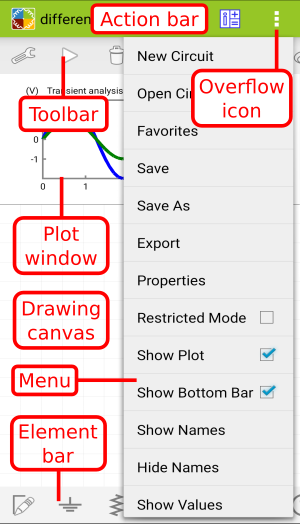
Basic user interface of the application consists of the Action bar, Toolbar, Element bar, Plot window, Menu, and Drawing canvas. The Menu can be opened by tapping the Overflow icon:
Toolbar Buttons
| Properties | |
| Quick Show V or I | |
| Run/Stop | |
| Delete | |
| Rotate Clockwise | |
| Flip Horizontally | |
| Undo | |
| Redo | |
| Bring to Front | |
| Send to Back | |
| Cut | |
| Copy | |
| Paste | |
| Select | |
| Select All | |
| Reset View | |
| Screenshot | |
| Previous Page | |
| Next Page |
Modifying User Interface
To modify the user interface, you can use the following commands.
Reset View
To scale the Drawing canvas to fit the whole circuit, tap the Reset View button from the Toolbar.
Zoom View
The Drawing canvas can be reduced or enlarged with a double-tap (if applicable) or a two-finger spread gesture.
Restricted Mode
If the Restricted Mode item from the Menu is checked, the view will be scaled to fit the whole circuit and the application will be switched to the Restricted mode.
Sim. Shows Plot
If the Sim. Shows Plot item from the Menu is checked, the Plot window will be displayed after the start of simulation. This window can be hid immediately by a fling gesture.
Show Bottom Bar
If the Show Bottom Bar item from the Menu is checked, the Element bar will be shown on the bottom.
Circuit Management
Circuits used in ECStudio are located in the internal directory.
Creating New Circuits
Choose New Circuit from the Menu. This opens an empty document in the Normal mode.
Saving Circuits
Use Save from the Menu to save the current circuit to the <app directory>.
Use Save As from the Menu to save the current circuit with a different file name to the <app directory>.
Opening Circuits
Use Open Circuit from the Menu to show Open Circuit dialog, allowing you to find a desired file and tap on its name. Or you can use Favorites to open a bookmark file. In the Open Circuit dialog you can delete, rename or bookmark (add to favorites) a file using the long tap gesture. There is also a search form to quickly search for a file.
Downloading Circuits
Use Web Circuits from the Menu to show Open Web Circuit window, allowing you to download a circuit from our web page. After tapping a circuit's screenshot in the window, the circuit is downloaded to the internal temporary directory. The circuit can then be saved to the <app directory> directory using the Save or Save As from the Menu.
Properties of Circuits
Choose Circuit Properties from the Menu to show Circuit Properties dialog, allowing you to change various settings of the current circuit.
Title
Enter a single-line title text.
Description
Enter a description text. This text is visible in Open Circuit dialog.
TRANSIENT ANALYSIS
The parameters of the Transient analysis are described in this video on YouTube.
Start
Start time for the Transient analysis.
Stop
Stop time for the Transient analysis.
Points
The number of points for the Transient analysis. It can be from 20 to 5000.
Use initial conditions
If checked, the simulator uses the initial values of appropriate elements entered using an extra parameter (IC=...) as the initial conditions in the Transient analysis.
Automatic times
If checked and the circuit contains Vsin and/or Vpulse sources, the start and stop times are calculated automatically from the periods of these sources.
Note:
The above Transient analysis parameters can be changed by a horizontal pinch gesture on the Plot window in the Continuous mode of simulation.
DC ANALYSIS
Start
Start voltage for the DC analysis.
Stop
Stop voltage for the DC analysis.
Step
Step voltage for the DC analysis.
Source
Select a name of the independent voltage source to be swept.
AC ANALYSIS
Start
Start frequency for the AC analysis.
Stop
Stop frequency for the AC analysis.
Points
The number of points for the AC analysis. It can be from 1 to 10000.
Type
Select a type of the x-axis. The LIN type makes the x-axis to be divided linearly. The DEC and OCT makes the x-axis to be divided logarithmically (by decades or octaves).
Analysis
Select a type of the analysis for the simulation. The most common analysis is the Transient analysis, which calculates (instantaneous) voltages and currents of the circuit as a function of time.
In the AC analysis, the frequency of sinusoidal voltage sources (Vsin) is swept over a user-specified range. The magnitude, real value, imaginary value and phase of (small-signal) voltages and currents are then calculated as a function of frequency. It follows that at least one sinusoidal voltage source is required for a meaningful AC analysis. Further, only Amplitude and Phase parameters of this source are used in the AC analysis.
In the DC analysis, a chosen DC voltage source is swept from the Start voltage to the Stop voltage in increments of the Step voltage. DC voltages and currents of the circuit are then calculated for each value of the sweep. It follows that at least one DC voltage source is required in the DC analysis.
Note:
In the DC and Transient analyses, only Real (instantaneous) number types can be used.
Force preserving voltages
If checked, the simulated voltages (and inductor currents) of the circuit will be preserved when changing a parameter value or when toggling a switch (or switchable source) in the Continuous mode of Transient analysis, regardless of the Preserve voltages app setting.
Force Gear integration
If checked, the SPICE integration method will be Gear, regardless of the Integration method app setting. Use this integration method, if you have problems with the convergence. The method is especially useful for circuits containing positive feedbacks, e.g. astable and monostable multivibrators.
Show grid
Adds gridlines to the X and Y axes of the circuit.
Grid color
Displays Select color dialog to set the color of gridlines.
Show pin numbers
Shows pin numbers of selected elements.
Canvas text color
Displays Select color dialog to set the color of pin numbers and label texts of newly created elements.
Canvas background color
Displays Select color dialog to set the color of Drawing Canvas.
Plot foreground color
Sets the color of Plot window.
Plot background color
Sets the color of texts and lines of the Plot window.
Box border color
Sets the color of label border.
Controls color
Displays Select color dialog to set the color of various control elements (scrollbars, cursor lines, etc.).
Wire color
Sets the color of wires and circuit junctions.
Symbol line width
Sets the width of element's lines. It can be between 0.2 and 20.
Symbol line color
Sets the color of element's lines (excluding wires).
Graph line width
Sets the width of graph lines. It can be between 1 and 10.
Minimum size of indicators
Sets the minimum relative size of current and voltage indicators. It can be between 0 and 1.
Maximum size of indicators
Sets the maximum absolute size of current (width) and voltage (radius) indicators in pixels. It can be between 1 and 100.
Box margins
Sets margins of all labels except Output labels.
Textbox margins
Sets margins of all Textbox elements.
IEC-style symbols
Displays IEC-style symbols.
Precision
Controls the precision of numerical results in the Output labels as well as in the Plot window. It can be from 2 to 10. The precision of results in the Plot window will be Precision + 1.
Reset properties (white or black theme)
Resets properties of the current circuit to the default values, except for Title and Description.
Elements
Each element can have attached several labels:
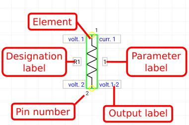
These labels are used to display simulation results, parameters of elements, or some text. When you move an element, its labels also move, but labels can be moved or rotated independently of elements. By rotating or flipping an element you can reset the position and rotation of the element's labels.
Labels
Labels can be of four types: Parameter labels, Text labels, Output labels, and Designation labels. Parameter labels are used to control the main parameter of elements. Text labels can be used only for showing a text. Output labels allow to display plots, indicators, graphs and numerical values of corresponding variables (voltages or currents). And finally, designation labels are used to mark elements.
Output labels
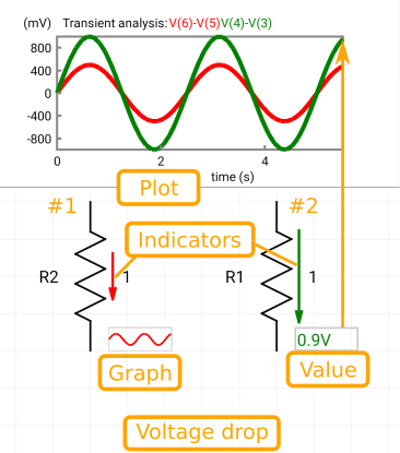
An Output label is always attached to a variable of the circuit. This variable can be a voltage, voltage drop or current. In the case of the voltage or current, the Output label belongs to one pin of the element and one node of the circuit. As the voltage drop is always determined between two points of the circuit, the Output label attached to a voltage drop belongs to two pins of the element and two nodes of the circuit.
The numerical value and graph of a variable attached to the Output label are displayed inside the label. The graph of a variable can be shown also in the Plot window, while a graphical representation (indicator) of the numerical value can be drawn in the element. The type of the variable, pin and node numbers pertaining to the Output label are shown in the top line of the Label Properties Dialog. Before simulation, Output labels contain a text, which show a type of the variable (volt. for voltage or voltage drop and curr. for current) and the pin numbers, for which the labels will display the variable values or graphs.
In the case of the voltage drop variable, the label belonging to this variable will display the voltage drop (difference) between two pins of the element. The numerical value displayed in the label is an absolute value, as the direction (sign) of the voltage is shown by an appropriate indicator:
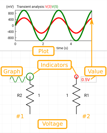
In the case of the voltage variable, the label belonging to this variable will display the voltage between the pin of the element and the ground:
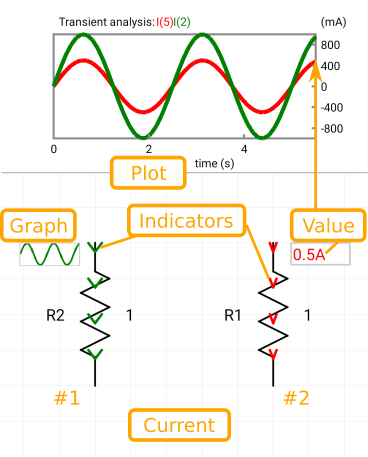
And in the case of the current variable, the label will display the current flowing to the pin of the element. The numerical value displayed in the label is an absolute value, as the current direction (sign) is shown by an appropriate indicator:
Indicators
Indicators are used for visual representation of simulated results. They are of three types: current indicators, voltage indicators, and voltage drop indicators.
![]()
Current indicators are drawn as colored arrows inside elements, which show the direction of the current through elements (in the Transient and DC analyses) or the sign of current (in the AC analysis). The width of arrows represents a relative magnitude of the current.
![]()
Voltage indicators are drawn as colored circles around the appropriate pin. The radius of a circle represents a relative magnitude of the voltage.
![]()
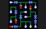
Voltage drop indicators are drawn as colored line arrows between appropriate pins. The length of an arrow represents a relative magnitude of the voltage drop. The line arrow also shows the direction of the voltage drop in the Transient and DC analyses, or the sign of drop in the AC analysis (see the example below).
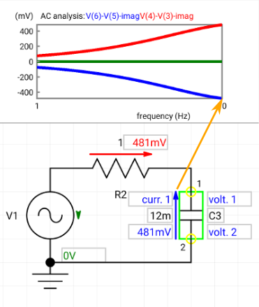
The picture above shows imaginary values of voltages across three elements in a simple circuit. As the voltage across the capacitor C3 points from pin 2 to pin 1 (blue arrow), which is the opposite direction comparing to its default direction, the value of this voltage is considered as negative. This corresponds to the negative value displayed on the top Plot window.
Note:
The phase type of a variable (no matter it is current or voltage) in the AC analysis is considered as a separated type of the variable for the purpose of calculation of relative magnitude. The relative magnitude of a variable is the ratio of the absolute value of the variable to the maximum absolute value of all active variables of the same type (current, voltage or phase). This maximum value is calculated through the whole simulation interval.
Note:
An Output label is active, if it has
at least one of these options checked in the Label Properties Dialog:
Show value, Show graph, Show indicator, Show plot. The variable belonging
to the active label is also considered as active.
Inserting Elements
The Element bar on the bottom of screen allows inserting these elements:
| Wire |
| See Drawing Wires. |
| Ground (Gnd) |
| Resistor |
| Parameter | Description |
|---|---|
| Resistance | Resistance in Ohms |
| Capacitor |
| Parameter | Description |
|---|---|
| Capacitance | Capacitance in Farads |
| Extra | The Extra parameter (IC=<volts>V) sets the initial (time = 0) value of capacitor voltage. Note that the initial conditions apply only if the Use initial conditions is checked on the Circuit Properties dialog. |
| Polarized capacitor |
| Parameter | Description |
|---|---|
| Capacitance | Capacitance in Farads |
| Extra | The Extra parameter (IC=<volts>V) sets the initial (time = 0) value of capacitor voltage. Note that the initial conditions apply only if the Use initial conditions is checked on the Circuit Properties dialog. |
| Inductor |
| Parameter | Description |
|---|---|
| Inductance | Inductance in Henries |
| Extra | The Extra parameter (IC=<amps>A) sets the initial (time = 0) value of inductor current that flows from pin 1, through the inductor, to pin 2. Note that the initial conditions apply only if the Use initial conditions is checked on the Circuit Properties dialog. |
| DC voltage source |
| Parameter | Description |
|---|---|
| Voltage | DC voltage of the source in the DC and Transient analyses. In the AC analysis, this source is a short circuit. |
| Pulse voltage source (Vpulse) |
| A voltage source usable in the Transient analysis. In the AC and DC analyses, this source is a short circuit. A single pulse of this source is described by the following table: |
| Time | Value |
|---|---|
| 0 | Initial |
| Delay | Initial |
| Delay + Rise | Pulsed |
| Delay + Rise + Width | Pulsed |
| Delay + Rise + Width + Fall | Initial |
| Period + Delay | Initial |
Note: If Rise and Fall times are 0, they will be set to the timestep, which is defined as (Stop - Start) / (Points - 1). |
| Sinusoidal voltage source (Vsin) |
| In the AC analysis, only Amplitude and Phase parameters of this source are used. In the Transient analysis, all parameters are used, and the Phase then represents the delay of the voltage. |
| DC current source |
| Parameter | Description |
|---|---|
| Current | DC current of the source in the DC and Transient analyses. In the AC analysis, this source is an open circuit. |
| Single-line text (Textbox) |
| Picture |
| Displays a Picture Selection window allowing to insert a jpg or png picture to the circuit. The maximum size of the picture is 1600x1600 pixels. |
| Parameter | Description |
|---|---|
| File | The name of the picture. Tapping this name will display the Picture Selection window. |
| Shift in x | The horizontal shift from the grid of the unrotated Picture element. |
| Shift in y | The vertical shift from the grid of the unrotated Picture element. |
| Diode |
| For description of the diode's main parameters (Saturation current, Ohmic-series resistance, Emission coefficient, Transit time, Junction capacitance), see here. |
| Parameter | Description |
|---|---|
| Extra | The Extra parameter (IC=<volts>) sets the initial voltage of the diode. Note that the initial conditions apply only if the Use initial conditions is checked on the Circuit Properties dialog. |
| Model | The filename of the diode model. See here. |
| Zener diode |
| For description of the diode's main parameters (Breakdown voltage, Saturation current, Ohmic-series resistance, Emission coefficient, Transit time, Junction capacitance), see here. |
| Parameter | Description |
|---|---|
| Extra | The Extra parameter (IC=<volts>) sets the initial voltage of the diode. Note that the initial conditions apply only if the Use initial conditions is checked on the Circuit Properties dialog. |
| Model | The filename of the diode model. See here. |
| LED diode |
| For description of the diode's main parameters (Saturation current, Ohmic-series resistance, Emission coefficient, Transit time, Junction capacitance), see here. The LED diode is presented also in this video on YouTube (time 14:20). |
| Parameter | Description |
|---|---|
| Color of effects | Displays the dialog for selection of the color of LED effects. When the Default button is tapped in this dialog, the color of the LED's effects will be the same as the color of the LED's current. |
| Extra | The Extra parameter (IC=<volts>) sets the initial voltage of the diode. Note that the initial conditions apply only if the Use initial conditions is checked on the Circuit Properties dialog. |
| Model | The filename of the diode model. See here. |
| Disable LED break | The app level setting, see it here. |
| Automatic lighting | The app level setting, see it here. |
| NPN transistor |
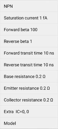
| For description of the transistors's main parameters (Saturation current IS, Forward beta BF, Reverse beta BR, Forward transit time TF, Reverse transit time TR, Base resistance RB, Emitter resistance RE, Collector resistance RC), see Wikipedia and SPICE documentation. |
| Parameter | Description |
|---|---|
| Extra | The Extra parameter (IC=<VBE>, <VCE>) sets the initial voltages (VBE and VCE) of the transistor. Note that the initial conditions apply only if the Use initial conditions is checked on the Circuit Properties dialog. |
| Model | The filename of the transistor model. See here. |
| The default values of parameters, when no model is selected: |
| Parameter | Default |
|---|---|
| Transport saturation current IS | 20 fA |
| Ideal maximum forward beta BF | 100 |
| Forward current emission coefficient NF | 1.0 |
| Forward Early voltage VAF | infinite |
| Corner for forward beta high current roll-off IKF | infinite |
| B-E leakage saturation current ISE | 0 |
| B-E leakage emission coefficient NE | 1.5 |
| Ideal maximum reverse beta BR | 1 |
| Reverse current emission coefficient NR | 1 |
| Reverse Early voltage VAR | infinite |
| Corner for reverse beta high current roll-off IKR | infinite |
| Leakage saturation current ISC | 0 |
| Leakage emission coefficient NC | 2 |
| Zero bias base resistance RB | 0.2 Ω |
| Current where base resistance falls halfway to its min value IRB | infinite |
| Minimum base resistance at high currents RBM | RB |
| Emitter resistance RE | 0 |
| Collector resistance RC | 0.2 Ω |
| B-E zero-bias depletion capacitance CJE | 20 pF |
| B-E built-in potential VJE | 0.75 V |
| B-E junction exponential factor MJE | 0.33 |
| Ideal forward transit time TF | 0.5 ns |
| Coefficient for bias dependence of TF - XTF | 0 |
| Voltage describing VBC dependence of TF - VTF | infinite |
| High-current parameter for effect on TF - ITF | 0 |
| Excess phase at freq=1.0/(TF*2PI) Hz - PTF | 0 |
| B-C zero-bias depletion capacitance CJC | 15 pF |
| B-C built-in potential VJC | 0.75 V |
| B-C junction exponential factor MJC | 0.33 |
| Fraction of B-C depletion capacitance connected to internal base node XCJC | 1 |
| Ideal reverse transit time TR | 10 ns |
| Zero-bias collector-substrate capacitance CJS | 0 |
| Substrate junction built-in potential VJS | 0.75 V |
| Substrate junction exponential factor MJS | 0 |
| Forward and reverse beta temperature exponent XTB | 0 |
| Energy gap for temperature effect on IS - EG | 1.11 eV |
| Temperature exponent for effect on IS - XTI | 3 |
| Flicker-noise coefficient KF | 0 |
| Flicker-noise exponent AF | 1 |
| Coefficient for forward-bias depletion capacitance formula FC | 0.5 |
| Parameter measurement temperature TNOM | 27 °C |
| PNP transistor |
| For description of the transistors's main parameters (Saturation current IS, Forward beta BF, Reverse beta BR, Forward transit time TF, Reverse transit time TR, Base resistance RB, Emitter resistance RE, Collector resistance RC), see Wikipedia and SPICE documentation. |
| Parameter | Description |
|---|---|
| Extra | The Extra parameter (IC=<VBE>, <VCE>) sets the initial voltages (VBE and VCE) of the transistor. Note that the initial conditions apply only if the Use initial conditions is checked on the Circuit Properties dialog. |
| Model | The filename of the transistor model. See here. |
| The default values of parameters, when no model is selected, are the same as for NPN transistor. |
| NMOS transistor |
| Parameter | Description |
|---|---|
| Treshold voltage | Zero-bias threshold voltage (VTO). VTO is positive for enhancement mode and negative for depletion mode N-channel MOS transistors. See Wikipedia. |
| Transconductance | Transconductance parameter (KP). |
| Lambda | Channel-length modulation. See Wikipedia. |
| Extra | The Extra parameter (IC=<VDS>, <VGS>, <VBS>) sets the initial voltages (VDS, VGS and VBS) of the transistor. Note that the initial conditions apply only if the Use initial conditions is checked on the Circuit Properties dialog. |
| Model | The filename of the transistor model. See here. |
| PMOS transistor |
| Parameter | Description |
|---|---|
| Treshold voltage | Zero-bias threshold voltage (VTO). VTO is negative for enhancement mode and positive for depletion mode P-channel MOS transistors. See Wikipedia. |
| Transconductance | Transconductance parameter (KP). |
| Lambda | Channel-length modulation. See Wikipedia. |
| Extra | The Extra parameter (IC=<VDS>, <VGS>, <VBS>) sets the initial voltages (VDS, VGS and VBS) of the transistor. Note that the initial conditions apply only if the Use initial conditions is checked on the Circuit Properties dialog. |
| Model | The filename of the transistor model. See here. |
| NJFET transistor |
| Parameter | Description |
|---|---|
| Treshold voltage | Threshold voltage (VTO), see Wikipedia. |
| Transconductance | Transconductance parameter (BETA). |
| Channel-length modulation | Channel-length modulation (LAMBDA), determines the output conductance. See Wikipedia. |
| Drain resistance | Drain ohmic resistance |
| Source resistance | Source ohmic resistance |
| Extra | The Extra parameter (IC=<VDS>, <VGS>) sets the initial voltages (VDS and VGS) of the transistor. Note that the initial conditions apply only if the Use initial conditions is checked on the Circuit Properties dialog. |
| Model | The filename of the transistor model. See here. |
| PJFET transistor |
| Parameter | Description |
|---|---|
| Treshold voltage | Threshold voltage (VTO), see Wikipedia. |
| Transconductance | Transconductance parameter (BETA). |
| Channel-length modulation | Channel-length modulation (LAMBDA), determines the output conductance. See Wikipedia. |
| Drain resistance | Drain ohmic resistance |
| Source resistance | Source ohmic resistance |
| Extra | The Extra parameter (IC=<VDS>, <VGS>) sets the initial voltages (VDS and VGS) of the transistor. Note that the initial conditions apply only if the Use initial conditions is checked on the Circuit Properties dialog. |
| Model | The filename of the transistor model. See here. |
| NOT logic gate |
| Parameter | Description |
|---|---|
| VCC | Power supply voltage |
| Threshold voltage | Threshold voltage of the gate's input |
| Output capacitance | Parallel capacitance placed at the gate's output |
| The output current is limited by a 200 Ω resistor. |
| AND logic gate |
| Parameter | Description |
|---|---|
| VCC | Power supply voltage |
| Threshold voltage | Threshold voltage of both inputs of the gate |
| Output capacitance | Parallel capacitance placed at the gate's output |
| The output current is limited by a 200 Ω resistor. |
| NAND logic gate |
| The internal schematic of the NAND gate is here. |
| Parameter | Description |
|---|---|
| VCC | Power supply voltage |
| Threshold voltage | Threshold voltage of both inputs of the gate |
| Output capacitance | Parallel capacitance placed at the gate's output |
| The output current is limited by a 200 Ω resistor. |
| OR logic gate |
| Parameter | Description |
|---|---|
| VCC | Power supply voltage |
| Threshold voltage | Threshold voltage of both inputs of the gate |
| Output capacitance | Parallel capacitance placed at the gate's output |
| The output current is limited by a 200 Ω resistor. |
| NOR logic gate |
| Parameter | Description |
|---|---|
| VCC | Power supply voltage |
| Threshold voltage | Threshold voltage of both inputs of the gate |
| Output capacitance | Parallel capacitance placed at the gate's output |
| The output current is limited by a 200 Ω resistor. |
| XOR logic gate |
| Parameter | Description |
|---|---|
| VCC | Power supply voltage |
| Threshold voltage | Threshold voltage of both inputs of the gate |
| Output capacitance | Parallel capacitance placed at the gate's output |
| The output current is limited by a 200 Ω resistor. |
| XNOR logic gate |
| Parameter | Description |
|---|---|
| VCC | Power supply voltage |
| Threshold voltage | Threshold voltage of both inputs of the gate |
| Output capacitance | Parallel capacitance placed at the gate's output |
| The output current is limited by a 200 Ω resistor. |
| SR latch |
| Parameter | Description |
|---|---|
| VCC | Power supply voltage |
| Threshold voltage | Threshold voltage of both inputs of the latch |
| Output capacitance | Parallel capacitance placed at the latch's Q output |
| Inverted output capacitance | Parallel capacitance placed at the latch's inverted output |
| The output current is limited by a 200 Ω resistor. |
| D flip-flop |
| Parameter | Description |
|---|---|
| VCC | Power supply voltage |
| Threshold voltage | Threshold voltage of both inputs of the flip-flop |
| Output capacitance | Parallel capacitance placed at the flip-flop's Q output |
| Inverted output capacitance | Parallel capacitance placed at the flip-flop's inverted output |
| The output current is limited by a 200 Ω resistor. |
| T flip-flop |
| The flip-flop realized using the master-slave JK flip-flop with K equal to J. |
| Parameter | Description |
|---|---|
| VCC | Power supply voltage |
| Threshold voltage | Threshold voltage of both inputs of the flip-flop |
| Output capacitance | Parallel capacitance placed at the flip-flop's Q output |
| Inverted output capacitance | Parallel capacitance placed at the flip-flop's inverted output |
| The output current is limited by a 200 Ω resistor. |
| JK flip-flop |
| The master-slave JK flip-flop. Its logic diagram can be found here. |
| Parameter | Description |
|---|---|
| VCC | Power supply voltage |
| Threshold voltage | Threshold voltage of all inputs of the flip-flop |
| Output capacitance | Parallel capacitance placed at the flip-flop's Q output |
| Inverted output capacitance | Parallel capacitance placed at the flip-flop's inverted output |
| The output current is limited by a 200 Ω resistor. |
| Advanced operational amplifier |
| Parameter | Description |
|---|---|
| Transconductance | Gain of the VCCS (2nd) stage. DC voltage gain (neglecting voltage limiting) is defined as Filter resistance * Transconductance. |
| Input resistance | The value of resistance (1st stage) placed between two inputs of the element. |
| Filter resistance | The value of resistance of the filter (3rd) stage. DC voltage gain (neglecting voltage limiting) is defined as Filter resistance * Transconductance. |
| Filter capacitance | The value of capacitance of the filter (3rd) stage. |
| Output resistance | The value of resistance placed at the element' output. |
| + supply voltage | Positive power supply voltage. |
| - supply voltage | Negative power supply voltage. |
| 555 timer |
| The output current is limited by a 100 Ω resistor. |
| LM317 |
| LM337 |
| 7805 |
| 7905 |
| Voltage controlled voltage source (VCVS) |
| Parameter | Description |
|---|---|
| Gain | Voltage gain |
| Voltage controlled current source (VCCS) |
| Parameter | Description |
|---|---|
| Transconductance | Transconductance |
| Current controlled voltage source (CCVS) |
| Parameter | Description |
|---|---|
| Transresistance | Transresistance |
| Current controlled current source (CCCS) |
| Parameter | Description |
|---|---|
| Gain | Current gain |
| Potentiometer 1 |
| Parameter | Description |
|---|---|
| Resistance | Resistance between end pins of the potentiometer |
| Wiper position | Relative position of the middle pin |
| Potentiometer 2 |
| Parameter | Description |
|---|---|
| Resistance | Resistance between end pins of the potentiometer |
| Wiper position | Relative position of the middle pin |
| Transformer |
| Parameter | Description |
|---|---|
| Coupling | Coupling coefficient, see Wikipedia. |
| Primary inductance | Inductance of the primary winding (pins 1 and 2) |
| Secondary inductance | Inductance of the secondary winding (pins 3 and 4) |
| Switch SPST |
| Switch SPDT |
| Open push-button |
| Closed push-button |
| Relay SPST |
| The relay's coil is polarized, and the current must flow from the upper terminal (+) to the lower one (of unrotated element) to be able to close the contacts. |
| Parameter | Description |
|---|---|
| Threshold voltage | Threshold voltage of the control coil |
| Hysteresis voltage | Hysteresis voltage of the control coil |
| On resistance | Resistance between closed contacts |
| Off resistance | Resistance between open contacts |
| Coil resistance | Resistance of the control coil |
| Coil inductance | Inductance of the control coil |
| Relay SPDT |
| The relay's coil is polarized, and the current must flow from the upper terminal (+) to the lower one (of unrotated element) to be able to close the contacts. |
| Parameter | Description |
|---|---|
| Threshold voltage | Threshold voltage of the control coil |
| On resistance 1 | Resistance between closed first pair of contacts |
| Off resistance 1 | Resistance between open first pair of contacts |
| On resistance 2 | Resistance between closed second pair of contacts |
| Off resistance 2 | Resistance between open second pair of contacts |
| Coil resistance | Resistance of the control coil |
| Coil inductance | Inductance of the control coil |
| DC motor |
| The motor model is inspired by the model from ecircuitcenter.com. |
| Misc menu |
| Voltmeter |
| Voltmeter can measure a characteristic value of the voltage across it: RMS (root mean square), Mean, Minimum, Maximum or Instantaneous. The type of displayed value is selected by the Mode parameter of this element. The voltmeter contains only a resistor and can be used only in Transient analysis.
The RMS, Mean, Minimum and Maximum values are calculated from the whole plotting interval. Note: It is not recommended to set the resistance of voltmeter to a value above 1000 GΩ, as SPICE is sensitive to big ratios of the largest value to the smallest value of the element of same type (R, L, C etc) in the circuit (maximum ratio can be about 1E15). |
| Ammeter |
| Ammeter can measure a characteristic value of the current flowing through it: RMS (root mean square), Mean, Minimum, Maximum or Instantaneous. The type of displayed value is selected by the Mode parameter of this element. The ammeter contains only a resistor and can be used only in Transient analysis.
The RMS, Mean, Minimum and Maximum values are calculated from the whole plotting interval. Note: It is not recommended to set the resistance of ammeter to a value below 1 mΩ, as SPICE is sensitive to big ratios of the largest value to the smallest value of the element of same type (R, L, C etc) in the circuit (maximum ratio can be about 1E15). |
| Ohmmeter |
| Ohmmeter can measure resistance of connected circuits in DC and Transient analyses. It uses a DC voltage source (V) presented between the terminals. When the connected circuit is active and the current I flows into the ohmmeter, it displays a negative number (-V/I). |
| Oscilloscope |
|
See our example videos here. Oscilloscope (or Chart element) can display various variables (voltages, currents, resistances...) as a function of time or other variable. The maximum number of displayed variables (lines) is 3. X-axis variable can be selected using the X parameter, the three y-axis variables can be set up by the Y1, Y2, and Y3 parameters. After tapping the name of the parameter (X, Y1, Y2, or Y3) in the menu of the Properties button, the window for editing variables will be displayed. Using the spinners (left) you can select one of the available variables or operators: Top field - this empty field clears the variable setting. The empty variable is simply ignored. Default - the variable depending on the type of analysis: time for Transient analysis, frequency for AC analysis and voltage for DC analysis. In other words, it is the same variable as for the x-axis of the Plot window. Number - the number, which can be inserted in the edit box (right) * - multiplication operator / - division operator + - addition operator - - subtraction operator V(x) - the voltage of the x node, if available V(x)-V(y) - the difference between voltages of nodes x and y, if available I(x) - the current of the x node, if available To show some voltages V(x.. and currents I(x) in the spinners, it is necessary to set the appropriate labels as active output labels. The final formula (value of a parameter) is created from individual variables or operators starting from the top. Notes: When you will redraw (change) the circuit AFTER editing X, Y1, Y2, and Y3 parameters, the voltages V(x.. and currents I(x) in these parameters may not be valid due to the node renumbering. This can be avoided by checking the Automatic repair of oscilloscopes option. Multiplication operator (*) can be skipped, for example 2*V(3) is the same as 2V(3). |
| Parameter | Description |
|---|---|
| Width | The width of the oscilloscope window in pixels. |
| Height | The height of the oscilloscope window in pixels. |
| X | The formula for calculating the values of x-axis. |
| Y1 | The formula for calculating the y-axis values of the first line. |
| Y2 | The formula for calculating the y-axis values of the second line. |
| Y3 | The formula for calculating the y-axis values of the third line. |
| X label | The label of the x-axis. If empty and the X parameter is set to "Default", the corresponding label will be added automatically. |
| Y1 label | The label of the first line (Y1). If empty, the corresponding label will be added automatically. |
| Y2 label | The label of the second line (Y2). If empty, the corresponding label will be added automatically. |
| Y3 label | The label of the third line (Y3). If empty, the corresponding label will be added automatically. |
| X unit | The basic unit of the x-axis. If empty and the X parameter is set to "Default", the corresponding unit will be added automatically. |
| Y1 unit | The basic unit of the y-axis values of the first line (Y1). |
| Y2 unit | The basic unit of the y-axis values of the second line (Y2). |
| Y3 unit | The basic unit of the y-axis values of the third line (Y3). |
| Y1 color | The color of the first line (Y1). |
| Y2 color | The color of the second line (Y2). |
| Y3 color | The color of the third line (Y3). |
| Y scale | The scale type of the y-axis. The "Linear" type makes the y-axis to be divided linearly. The "Logarithmic" makes the y-axis to be divided logarithmically (by decades). |
| Xmax scale | This parameter is used to increase or decrease the maximum value on the x-axis. The original maximum value (obtained from the simulated values) will change by (Xmax scale - 100) percent of the original interval (maximum - minimum). |
| Xmin scale | This parameter is used to increase or decrease the minimum value on the x-axis. The original minimum value (obtained from the simulated values) will change by (Xmin scale - 100) percent of the original interval (maximum - minimum). |
| Ymax scale | This parameter is used to increase or decrease the maximum value on the y-axis. The original maximum value (obtained from the simulated values) will change by (Ymax scale - 100) percent of the original interval (maximum - minimum). |
| Ymin scale | This parameter is used to increase or decrease the minimum value on the y-axis. The original minimum value (obtained from the simulated values) will change by (Ymin scale - 100) percent of the original interval (maximum - minimum). |
| Font size | The relative size of the font used to draw texts and numbers on the oscilloscope window. |
| Line style | The style of the plotted curves. |
| Line width | The width of the plotted curves in pixels. |
| Grid lines | If set to "On", adds gridlines to the X and Y axes of the oscilloscope. |
| Grid line width | The width of the gridlines in pixels. If set to 0, "hairlines" will be drawn. |
| Grid line color | The color of the gridlines. |
| Frame line width | The line width of the frame surrounding the chart area. |
| Axes | If set to "On", the coordinate axes will be shown. |
| Axis line width | The width of the axis line in pixels. If set to 0, "hairlines" will be drawn. |
| Axis line color | The color of the axis line. |
| Numeric precision | The precision of the numbers drawn on the oscilloscope window. |
| Data | Shows the window containing the last simulated data. |
| Switchable source |
| DC voltage source, which can be switched between 0 V (logic 0) and 5 V (logic 1) by a long tap. |
| 7-segment display |
| Display device used for displaying decimal numerals. Each segment of the display will light if its input voltage is above 2.5 V. |
| Parameter | Description |
|---|---|
| Digit color | Displays the dialog for selection of the color of digits. |
| 7-segment decoder |
| BCD to 7-segment decoder. |
| Parameter | Description |
|---|---|
| VCC | Power supply voltage |
| Threshold voltage | Threshold voltage of inputs |
| Crossover |
| Parameter | Description |
|---|---|
| Resistance | Resistance between pins of the element |
| Crossover 2 |
| Parameter | Description |
|---|---|
| Resistance | Resistance between pins of the element |
| Fuse |
| A fuse is the simplest circuit protection device used to stop
current flow or open the circuit, when the circuit current exceeds
the current rating of fuse (maximum current). Note: The fuse effects (fuse "blowing") works only in Continuous ("Run") mode of Transient and DC analyses. |
| Parameter | Description |
|---|---|
| Maximum current | The maximum current of a fuse is a value expressed in amperes that represents the current the fuse will allow without opening (“blowing”). |
| Speaker |
| The model of Speaker consists of five elements. Two elements (Series resistance and Series inductance) are in series. These two elements are then in series with the remaining elements (Parallel resistance, Parallel inductance and Parallel capacitance), which are connected in parallel. |
| Lamp |
| See the lamp effects setting here. |
| Parameter | Description |
|---|---|
| Color of effects | Displays the dialog for selection of the color of lamp effects. When the Default button is tapped in this dialog, the color of the lamp's effects will be the same as the color of the lamp's current. |
| Voltage | Nominal voltage |
| Resistance | Nominal resistance |
| Automatic lighting | The app level setting, see it here. |
| Opamp |
| Simple operation amplifier |
| Parameter | Description |
|---|---|
| Gain | Differential voltage gain |
| Input resistance | The value of resistance placed between two inputs of the Operation amplifier. |
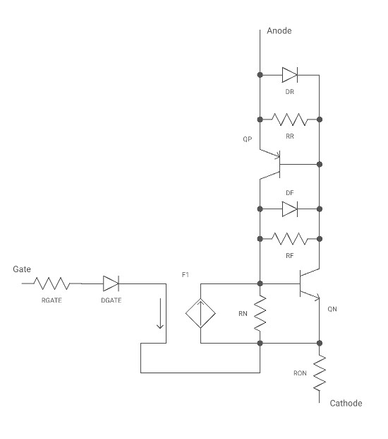
| SCR |
| Silicon controlled rectifier (Vol. III - Semiconductors textbook). The model is shown below. |
| Parameter | Description |
|---|---|
| Gate resistance | RGATE's resistance |
| Gate stage gain | Current gain of F1 (Current-Controlled Current Source). It can be used to adjust the SCR's trigger current. |
| NPN B-E resistance | RN's resistance. It can be used to adjust the SCR's holding current. It influences also the SCR's trigger current. |
| PNP B-E resistance | RR's resistance |
| ON resistance | RON's resistance |
| Breakdown voltage | Breakdown voltage of DF and DR. It may be used to control the breakover voltage between anode and cathode. |
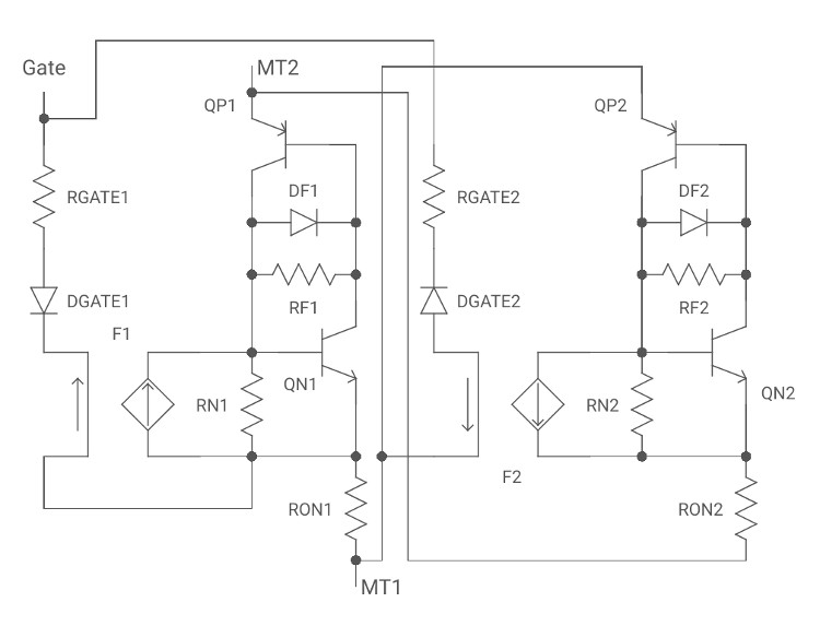
| TRIAC |
| Bidirectional thyristor — two joined SCRs (Vol. III - Semiconductors textbook). The model is shown below. |
| Parameter | Description |
|---|---|
| Gate resistance 1 | RGATE1's resistance |
| Gate stage gain 1 | Current gain of F1 (Current-Controlled Current Source). It can be used to adjust the SCR1's trigger current. |
| NPN B-E resistance 1 | RN1's resistance. It can be used to adjust the SCR1's holding current. It influences also the SCR1's trigger current. |
| ON resistance 1 | RON1's resistance |
| Gate resistance 2 | RGATE2's resistance |
| Gate stage gain 2 | Current gain of F2 (Current-Controlled Current Source). It can be used to adjust the SCR2's trigger current. |
| NPN B-E resistance 2 | RN2's resistance. It can be used to adjust the SCR2's holding current. It influences also the SCR1's trigger current. |
| ON resistance 2 | RON2's resistance |
| Breakdown voltage | Breakdown voltage of DF1 and DF2. It may be used to control the breakover voltage between MT1 and MT2. |
| Advanced text |
| Webview object allowing to display a html text. User interaction (e.g. clicking links) is disabled in the Restricted mode. |
| IC menu |
| Custom digit-pin |
| Custom subcircuits, integrated circuits or other component, see here. digit is the number of pins of the component. |
| Custom opamp 1 |
| Custom operational amplifier or other component with 5 pins, see here. |
| Custom opamp 2 |
| Custom operational amplifier or other component with 7 pins, see here. |
| Custom opamp 3 |
| Custom operational amplifier or other component with 3 pins, see here. |
| Custom regulator |
| Custom voltage regulator or other component with 3 pins, see here. |
| Custom element |
| Custom element similar to the above custom elements, however it has the editor of the symbol. It allows to create an element with custom number of pins. See this youtube video. |
| Web Components |
| Displays the window for selecting various components or subcircuits found on our web. |
Elements are inserted into the grid with a cell size of 100x100 pixels. The center of the picture element is always positioned at an intersection of gridlines.
Models of transistors and diodes can be selected by tapping the Model parameter of elements and selecting a model from the System Models section of the Model dialog. The values of numerical parameters entered through the Element Properties Menu will then be ignored.
Models of transistors and diodes can be selected also using Custom elements. The app accepts SPICE 3 format of the models.
Example models:
1N4004 - standard rectifier diode
1N4148 - small signal diode
2N2222 - general purpose NPN transistor
BC547A - general purpose NPN transistor
2N2907 - general purpose PNP transistor
J111 - N-channel JFET switch
IRF530 - power N-channel MOSFET
Note:
By a long tap on an element button you can display the name of the element.
Drawing Wires
To draw a wire, tap the Wire button in the Element bar and then tap the start and end points of the wire to be drawn. If these points do not lie on a vertical or horizontal line, the wire will be drawn using autorouting, otherwise a simple one-line wire will be created.
Selecting Elements
Select Element
To select only one element, tap some place on the element outside of the element's labels. All labels attached to the element are then displayed, and a Selection rectangle will be drawn around the element. If the "Rectangle selection" is not checked in the Menu->App Settings, the selected element will be instead painted by a Selection color.
To select multiple elements, tap the Select button in the Toolbar and then tap the top left-hand as well as bottom right-hand corners of the area containing the elements to be selected.
Deselect Element
To deselect only one element, tap some place on the element outside of the element's labels.
To deselect multiple elements, tap the Select button in the Toolbar and then double tap some place outside the circuit elements.
Select All Elements
To select all circuit elements, tap the Select All button in the Toolbar.
Select Label
To select a label, tap the element to which the label is attached and then tap the label. A red rectangle will be drawn around the label.
Moving Elements and Labels
Moving Elements
To move selected elements, tap and drag them to a new position. Elements are snapped to the grid.
Moving Labels
To move the selected label, long tap and drag it to a new position. Labels can be moved to any place of the Drawing canvas.
Editing Elements
Properties Button
The multipurpose Properties button in the Toolbar allows users to set properties of elements, labels or simulation. If there is no selected element, it shows the seek bar used to control the speed of displaying of simulation results in the Continuous mode of simulation. If a label is selected, it displays the Label Properties Dialog allowing to set properties of the label. If only one element is selected and none of its labels are marked, it displays the Element Properties Menu allowing to set parameters of the element.
Element Properties Menu
The first line of the menu is always the name of the element. The last two lines are always the Edit (see this youtube video) and Add to menu (save) commands. The Add to menu command allows adding the selected element into the Available list of the Custom menu editor. The lines between the first and the last two lines represent the properties of the element. By tapping on some of these lines (if there is any) you can display a parameter window with a scrollbar and buttons allowing to set the chosen parameter:
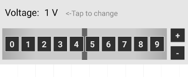
Scrolling the bar (tapping any place of the horizontal ribbon and moving the finger) to the right is used to increase the parameter's value by a small amount, while scrolling this bar to the left decreases the parameter's value. Tapping the 0 button sets the value to 0 (if possible). Tapping any digit from 1 to 9 sets the particular value in the current decade (if possible). + and - buttons are used to multiply the value by 10 and 1/10, respectively. By tapping the name of the parameter you can set the parameter's value through a text dialog.
If "Native parameter's scrollbar" in the App settings is checked, the native scrollbar with two spinners are shown instead of the default parameter window shown above:
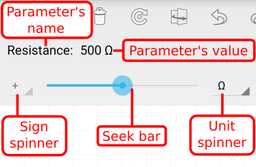
This scrollbar has increment of 1 and is used especially for quick changes of parameters. The left-hand spinner can be used to change the sign of the parameter, while the right-hand spinner is used for selecting a unit of the parameter. By tapping the name of the parameter you can set the parameter's value through a text dialog.
Note:
For textual parameters (e.g. Model filenames), the seek bar and spinners are purposefully hidden.
Edit Command
The Edit item in the Element Properties Menu allows users to edit various properties of elements.
Diode model
All diodes with the model named APPLICATIONDIODE in the subcircuit of
a Custom element will use a model selected in the Diode model dialog.
Zener diode model
All diodes with the model named APPLICATIONZENER
in the subcircuit of a Custom element will use a model selected in the Zener diode model dialog.
LED model
All diodes with the model named APPLICATIONLED
in the subcircuit of a Custom element will use a model selected in the LED model dialog.
NPN transistor model
All transistors with the model named APPLICATIONNPN
in the subcircuit of a Custom element will use a model selected in the NPN transistor model dialog.
PNP transistor model
All transistors with the model named APPLICATIONPNP
in the subcircuit of a Custom element will use a model selected in the PNP transistor model dialog.
NMOS transistor model
All transistors with the model named APPLICATIONNMOS
in the subcircuit of a Custom element will use a model selected in the NMOS transistor model dialog.
PMOS transistor model
All transistors with the model named APPLICATIONPMOS
in the subcircuit of a Custom element will use a model selected in the PMOS transistor model dialog.
NJFET model
All transistors with the model named APPLICATIONNJFET
in the subcircuit of a Custom element will use a model selected in the NJFET model dialog.
PJFET model
All transistors with the model named APPLICATIONPJFET
in the subcircuit of a Custom element will use a model selected in the PJFET model dialog.
Digital technology
All pseudo-elements (beginning with the letter X) with the names APPLICATIONAND,
APPLICATIONNAND, APPLICATIONOR, APPLICATIONNOR, APPLICATIONXOR, APPLICATIONXNOR,
APPLICATIONNOT, APPLICATIONSCHMITT, APPLICATIONDFLIPFLOP or APPLICATIONJKFLIPFLOP
in the subcircuit of a Custom element will use a model of digital technology (logic family, e.g. 74LS or
CMOS 4000) selected in the Digital technology dialog. The type of the model (analog or event-driven) can
be selected in the App Settings (see here). Call lines of these pseudo-elements:
AND gate:
XYYYYYYY N1 N2 ... N10 N11 N12 APPLICATIONAND
where
N1, N2 ... N10 - from 2 to 10 input nodes
N11 - output node
N12 - supply voltage
NAND gate:
XYYYYYYY N1 N2 ... N10 N11 N12 APPLICATIONNAND
where
N1, N2 ... N10 - from 2 to 10 input nodes
N11 - output node
N12 - supply voltage
OR gate:
XYYYYYYY N1 N2 ... N10 N11 N12 APPLICATIONOR
where
N1, N2 ... N10 - from 2 to 10 input nodes
N11 - output node
N12 - supply voltage
NOR gate:
XYYYYYYY N1 N2 ... N10 N11 N12 APPLICATIONNOR
where
N1, N2 ... N10 - from 2 to 10 input nodes
N11 - output node
N12 - supply voltage
XOR gate:
XYYYYYYY N1 N2 ... N10 N11 N12 APPLICATIONXOR
where
N1, N2 ... N10 - from 2 to 10 input nodes
N11 - output node
N12 - supply voltage
XNOR gate:
XYYYYYYY N1 N2 ... N10 N11 N12 APPLICATIONXNOR
where
N1, N2 ... N10 - from 2 to 10 input nodes
N11 - output node
N12 - supply voltage
NOT gate:
XYYYYYYY N1 N2 N3 APPLICATIONNOT
where
N1 - input node
N2 - output node
N3 - supply voltage
Inverting Schmitt trigger:
XYYYYYYY N1 N2 N3 APPLICATIONSCHMITT
where
N1 - input node
N2 - output node
N3 - supply voltage
D flip-flop:
XYYYYYYY N1 N2 N3 N4 N5 N6 N7 APPLICATIONDFLIPFLOP
where
N1 - D input
N2 - CLK input
N3 - Q output
N4 - Q output
N5 - supply voltage
N6 - Reset (Clear)
N7 - Set (Preset)
JK flip-flop:
XYYYYYYY N1 N2 N3 N4 N5 N6 N7 N8 APPLICATIONJKFLIPFLOP
where
N1 - J input
N2 - K input
N3 - CLK input
N4 - Q output
N5 - Q output
N6 - supply voltage
N7 - Reset (Clear)
N8 - Set (Preset)
Example of AND gate with three inputs:
X1 1 2 3 4 5 APPLICATIONAND
where
1,2,3 - input nodes
4 - ouput node
5 - supply voltage (should be connected to a voltage source, e.g. 5V for 74LS technology)
Switch element
This command allows to add a comma separated list of names of web elements (i.e. elements
found in the Web Components dialog - only elements with the name "Custom element" are allowed in this list),
which will be available in the Element Properties Menu. After selecting an element from this menu,
the current element will be deleted (excluding "Switch element" and "Custom name" commands) and replaced
with the selected element from the menu.
Logic IC effects
This command allows to add a logic state indicator into the Custom element.
Voltage indicator
This command allows to add a voltage output label into the Custom element.
The parameters name, positions, rotations and anchors are similar as for the text labels.
The other parameters:
indicators: (x1 y1)(x2 y2)(size) - x1 and y1 are coordinates of
the voltage indicator (circle). x2, y2 and size are not used now.
text: a text shown in the label before simulation.
pin: a pin associated with this output label.
Voltage drop indicator
This command allows to add a voltage drop output label into the Custom element.
The parameters name, positions, rotations and anchors are similar as for the text labels.
The other parameters:
indicators: (x1 y1)(x2 y2)(size) - x1 and y1 are coordinates
of the starting point of the voltage drop indicator (arrow). x2 and y2 are coordinates
of the ending point of the voltage drop indicator (arrow). size is not used now.
text: a text shown in the label before simulation.
pin: pin1Number pin2Number - the numbers of pins associated with this output label.
Current indicator
This command allows to add a current output label into the Custom element.
The parameters name, positions, rotations and anchors are similar as for the text labels.
The other parameters:
indicators: (x1 y1)(x2 y2)(size) - x1 and y1 are coordinates
of the starting point of the current indicator (arrow). x2 and y2 are coordinates
of the ending point of the current indicator (arrow). size is not used now.
text: a text shown in the label before simulation.
pin: a pin associated with this output label.
Label Properties Dialog
Show text (value)
Displays the text/value in the label. In the case of an Output Label, this option can be automatically reverted, depending on the "Graph/number switching" option in the App Settings.
Show box
Displays the box in the label.
Show graph
Displays the graph in the label instead of the box and text. This option is shown only in the case of an Output Label and can be automatically reverted, depending on the "Graph/number switching" option in the App Settings.
Show indicator
Draws the indicator in the element. This option is shown only in the case of an Output Label.
Show plot
Draws the graph in the plot window. This option is shown only in the case of an Output Label.
Cursors 1
If checked, after finishing a Common mode simulation the seek bar of the first cursor will be opened below the plot window. The cursor can be used to obtain x and y values of the corresponding graph. This option is shown only in the case of an Output Label.
Cursors 2
If checked, after finishing a Common mode simulation the seek bar of the second cursor will be opened below the plot window. The cursor can be used to obtain x and y values of the corresponding graph. This option is shown only in the case of an Output Label.
Number type
Select the type of corresponding current or voltage variable. In the AC analysis, you can display the magnitude, real value, imaginary value and phase of voltages and currents. In the DC and Transient analyses, only real (instantaneous) values can be displayed. This option is shown only in the case of an Output Label.
Scale
Enter a scale of the label.
Rotation
Select a rotation of the label.
Alignment
Select an alignment of the text inside the label.
Designation
Enter a designation of the element. This item will be shown only in the case of a Designation label.
Value
Enter a value of the label. This item will be shown only in the case of a Parameter label.
Text
Enter a text of the label. This item will be shown only for text elements.
Background color
Choose a color of the label's box.
Foreground color
Choose a color of the label's text. In the case of an Output label, this item is not shown as the foreground color is chosen automatically. The same color will be used in the graph as well as Plot window.
Rounded box
If checked, the label's box will be drawn rounded.
Font
Select a font type of the label's text.
Toolbar Commands
The next commands from the Toolbar can be applied to one or more selected elements.
Cut
Copies the selected elements to the clipboard and removes them from the current circuit.
Copy
Copies the selected elements to the clipboard.
Paste
Inserts the contents of the clipboard at a free location.
Delete
Removes the selected elements from the current circuit.
Bring to Front
Select the elements you want to bring to front, and then tap the Bring to Front button.
Send to Back
Select the elements you want to send to back, and then tap the Send to Back button.
Rotate Clockwise
You can rotate all elements along with the labels, except for wires. Select the elements you want to rotate, and then tap the Rotate Clockwise button. Labels are also rotated, according to the definition in the internal library file.
Flip Horizontally
You can flip all elements along with the labels, except for wires. Select the elements you want to flip, and then tap the Flip Horizontally button. Labels are also flipped, according to the definition in the internal library file.
Tools Commands
The next commands from the Menu->Tools can be applied only to all circuit elements.
Show Names
Shows the designations of the current circuit elements.
Hide Names
Hides the designations of the current circuit elements.
Show Values
Shows the values of the current circuit elements.
Hide Values
Hides the values of the current circuit elements.
Clear Web Circuits cache
Deletes text and picture files downloaded through the Web Circuits window.
Disable tips after restart
Hides all tips. A restart of the app may be needed.
Enable tips after restart
Shows all tips. A restart of the app may be needed.
Quick Show Button
Quick Show (EYE) button from the Toolbar can be used to quickly show some voltages and currents of the circuit. If only one 2-pin element is selected, it toggles displaying the indicator, value and plot of the element's current. If a logic IC (gate, SR latch or flip-flop) is selected, it toggles displaying the value and plot of the element's output voltage. If a wire is selected, it toggles displaying the plot and value of the wire's voltage. When no element is selected, it toggles displaying current indicators of wires. Moreover, the EYE button temporarily displays all non-active labels.
Notes:
If the "Graph/number switching" is checked in the Menu->App Settings, the displayed value can switch to the graph in the Transient analysis, when the value is not a constant in time. If the "Highlight wires" is checked in the Menu->App Settings and the voltage of a wire is set to show, the wire will be painted by the plot color.
Creating custom elements and subcircuits
To create a custom subcircuit, integrated circuit or other element, select the IC button of the Element bar on the bottom of screen and then a Custom ... item. Use the Properties button in the Toolbar to set the symbol, definition of the element (subcircuit), and its picture.
Symbol
The Custom element will display the editor of the symbol. See this youtube video.
After tapping the Symbol parameter of some other custom element (e.g. Custom 2-pin), the Symbol Selection window for choosing the look of the element will appear. If you select the Empty symbol, the look of the element can be changed using the Picture parameter.
Subcircuit
After tapping the Subcircuit parameter of the custom element, the Subcircuit window for setting the definition of the element (or subcircuit) will appear. The definition of the element can be loaded from the clipboard. By tapping the Paste button, the content of the clipboard will be loaded into the bottom Edit text area. After checking the definition of the element in this text area, you can tap the Set subcircuit button to apply the definition to the element. When you tap the Clear ("X") button, the text area will be cleared.
The definition of the subcircuit should be in the standard Berkeley SPICE 3 format. The subcircuits of various elements can be found on many web sites. If you are not sure, whether the found subcircuit has the right format, check it with the Berkeley web site. The subcircuit can have only elements and parameters found on this web site. Moreover, the ECStudio has some additional restrictions on subcircuits:
- Node, element and model names cannot contain the reserved string pterm9
- Semiconductor resistors and capacitors as well as time-dependent V and I sources are not supported
- Pins of subcuircits should not be connected directly to the node 0
Picture
By tapping the Picture parameter of the custom element, the Picture Selection window for choosing the look of the element will appear. The center of the selected picture will be positioned in the center of the Default symbol (except for the Custom 8-pin, Custom 12-pin and Custom 16-pin elements, when the picture's center will be 50 pixels (half of the grid height) below the center of the Default symbol. Only .jpg and .png pictures are supported. The maximum size of the picture is 1600x1600 pixels.
Switching Switches
The switches (Switch SPST, Switch SPDT, Open push-button and Closed push-button) can be switched by long tapping the switch.
Undo and Redo
Undo
Reverses the last editing command or the last change of a property.
Redo
Reverses the action of the last Undo command.
Simulation
Running Simulation
Tap Run/Stop button in the Toolbar. This opens the menu of two items. The item Run starts the Continuous mode of simulation of a type chosen in the Properties dialog, when the results are displayed consecutively with a user controlled speed. In the case of DC and AC analyses, the simulation will stop after displaying of the last result. In the case of Transient analysis, the simulation is run repeatedly with a gradually increasing start time of the simulation.
The item Run and Show All starts the Common mode of simulation of a type chosen in the Properties dialog. After finishing the simulation all results are displayed immediately.
When a simulation is running, it can be stopped (or paused in the case of the Pause mode) by tapping on the Run/Stop button. In the Continuous mode, the displaying of results is then paused and these results can be thereafter explored. The next tap of the Run or Run and Show All item starts a new simulation.
Note:
At least one Gnd element is required to achieve a successful simulation.
Export/Import and Screenshots
Export/Import Dialog
Use Export/Import item from the Menu to open Export/Import dialog.
Exporting the image
Exports the image of the current circuit to the device's gallery.
Max. scaling factor
Down-size the image to a lower resolution. The size of target images depends on the available memory.
Quality
Enter the quality level for JPEG compression.
File name
Enter a file name for the image.
Exporting the current circuit...
Exports the current circuit to the device's storage.
Exporting all your circuits...
Exports all your circuits to the device's storage.
Importing a circuit...
Shows a dialog for opening a circuit from the device.
Importing selected circuits...
Shows a dialog for copying selected circuits to the internal app directory.
Screenshot
Tapping the Screenshot button takes a screenshot and places it to the device's gallery.
View menu
Use View item from the Menu to open submenu allowing to show and export simulator log, application log and output data.
App Settings
Choose App Settings from the Menu to show the dialog allowing you to change various settings of the application. The Overflow icon of this dialog allows to select the Basic or Advanced part of the dialog.
Basic
Language
The app language. A restart of the application is needed to apply the change. In some old versions of Android, the Force Stop may be necessary.
Graph/number switching
If checked, Output labels will be switched between showing graph or value (number) in the Transient analysis. Then, if an Output label will be showing horizontal line for some time, the label will start to show the value.
Highlight wires
If checked, all wires set to show the voltage will be painted by the plot color.
Highlight adjacent wires
If checked, the wire connected to some output wire (i.e. wire set to show the voltage) directly or indirectly through other wires will be painted by the same plot color as this output wire.
Wire indicator color
The color of indicators of wire current shown by the Quick Show (EYE) button.
Wire color
The color of wires.
Activate wire color
If checked, the Wire color will be used instead of the color set in Circuit Properties.
Symbol color
The color of symbols of elements.
Activate symbol color
If checked, the Symbol color will be used instead of the color set in Circuit Properties.
Node color
The color of nodes (dots).
Activate node color
If checked, the Node color will be used instead of the color set in Circuit Properties.
Plot color 1...5
The colors of graph lines and numerical results. The default plot colors (from plot color 1 to 5): Green (#008000), Red (#ff0000), Blue (#0000ff), Saddle Brown (#8b4513), Purple (#800080).
Current indicators
The shape of indicators of current.
Current indicator type
The type of indicators of current.
Voltage drop indicator
The shape of indicators of voltage drop.
Non-transparent graphs
If checked, the transparency of all circuit graphs will be removed (i.e. alpha channel of the graph background color will be set to 255). The other components (red, green, blue) of the graph background color will be the same as components of the Canvas background color.
App theme
Theme of the application. A restart of the application is needed to apply the change.
Theme
Theme of the newly created circuits.
Apply Theme when opening circuits
If checked, the Theme is applied to the circuit right after the opening and the text and box colors of all circuit's labels are also rewritten according to the Theme. This operation can be reversed by the Undo button.
Note:
The circuits (pages) of the Interactive book are not affected by this option. This may change in the future.
Rectangle selection
If checked, selected elements will be highlighted by the rectangle. In the opposite case, they will be painted with the Selection color.
Selection color
Sets the color of selected elements and the selection rectangle.
Disable nonactive labels
If checked, non-active output labels will never be shown. Non-active output labels can then be activated only using the EYE button.
Disable labels in Restricted mode
If checked, non-active output labels will never be shown in Restricted mode. Non-active output labels can then be activated only using the EYE button.
Native parameter's scrollbar
If checked, the native scrollbar will be used for setting the parameters of elements.
LED effects
If checked and the LED diodes are set to show the current or Automatic lighting is checked, the diodes will be glowing. The intensity of glowing depends on the LED's current. After reaching "break" current (2.5*Imax), the LED will show "break" effect, see the video on YouTube here (time 14:20).
LED max current
The current at which the LED's glowing is maximum.
Disable LED break
If checked, the LED will not "break" and will glow at all currents above LED max current.
Automatic lighting
If checked, LED diodes and lamps will be glowing even if they are not set to show the current.
Lamp effects
If checked and the lamps are set to show the current or Automatic lighting is checked, the lamps will be glowing. The intensity of glowing depends on the lamp's current. Maximum intensity is reached at the current I = Voltage / Resistance
Logic IC effects
If checked and the logic ICs (gates, SR latch or flip-flops) are set to show the output voltage, the ICs will show graphically a logic level of the output voltage: "1" or "H" (see Logical numbers) for a voltage above the IC's threshold voltage, "0" of "L" for a lower voltage.
Automatic IC effects
If checked, the logic ICs (gates, SR latch or flip-flops) will show graphically an output logic level even if they are not set to show the voltage.
Custom logic IC effects
If checked, the custom ICs having a logic symbol will show a logic level of the output voltage: "1" or "H" (see Logical numbers) for a voltage above the threshold voltage, "0" or "L" for a lower voltage.
Preserve voltages
If checked, the simulated voltages (and inductor currents) of the circuit will be preserved when changing
a parameter value or when toggling a switch (or switchable source) in the Continuous mode of Transient analysis. If this setting is not checked, the voltages and currents can be preserved using the Preserve voltages for switches option.
This "experimental mode" should be used only for simple circuits, especially to study transient effects of L and C charging or to observe the switching of bistable circuits. In this mode, the pulsed voltage sources (Vpulse) have always zero rise and fall times.
Note:
Even though this mode is denoted as "experimental", it should work for all properly defined circuits. However, in the case of some more complex circuits, it may be necessary to increase the precision of simulation, e.g. by decreasing the Relative and Transient tolerance to about 1m and 7, respectively.
Preserve voltages for switches
If checked and the circuit contains a switch or switchable source, the simulated voltages (and inductor currents) of the circuit will be preserved when changing a parameter value or when toggling a switch (or switchable source) in the Continuous mode of Transient analysis.
Check for ground
If checked and the current circuit does not contain Gnd
elements or internally grounded elements, the circuit will not be simulated.
The list of internally grounded elements: logic gates, flip-flops, 555 timer,
controlled sources, opamp, advanced opamp, transformer, relays, switched source,
7-segment display, 7-segment decoder.
Absolute tolerance
Increasing this value from the default (1p) can help to resolve SPICE convergence problems. It is the ABSTOL SPICE option - absolute current error tolerance.
Voltage tolerance
Voltage error tolerance. Increasing this value from the default (1E-6) can help to resolve SPICE convergence problems. It is the VNTOL SPICE option.
Relative tolerance
Relative error tolerance. The default value (5m) is higher than the standard value (1m) to overcome convergence problems. Decrease it to about 1m to get higher precision (in some cases). See this video on YouTube. It is the RELTOL SPICE option.
Transient tolerance
Transient error tolerance. The default value (100) is higher than the standard value (7) to overcome convergence problems. Decrease it to about 7 to get higher precision in Transient analysis (in some cases). See this video on YouTube. It is the TRTOL SPICE option.
Iteration limit
Transient analysis timepoint iteration limit. The default value is 50. It is the ITL4 SPICE option.
Minimum conductance
The minimum conductance allowed by the app. The default value is 100p. It is the GMIN SPICE option.
Integration method
The integration method of SPICE, see here. Use Gear integration method, if you have problems with the convergence. This method is especially useful for circuits containing positive feedbacks, e.g. astable and monostable multivibrators. The default (Trap) method is both faster and more accurate than Gear.
Tmax divider
Tmax divider can be used to increase the maximum computing interval in Transient analysis. The maximum computing interval is defined as Display interval / Tmax divider, where Display interval is (Stop - Start) / (Points - 1).
Reset EEA Consent
When tapped, European users can set the EEA consent after restarting the application.
Advanced
Use ngspice
If checked, the ngspice simulator will be used instead of Spice 3. If the circuit contains custom elements with at least one line starting with "a" or "A" ("XSPICE" line), ngspice will be used regardless of this option. See the XSPICE documentation for more info about these lines.
At the start of the simulation, ngspice loads these libraries: analog.cm, digital.cm, spice2poly.cm, xtradev.cm and xtraevt.cm.
Activate rshunt
If checked, the ngspice simulator inserts "rshunt" resistors to ground at all nodes of the circuit, which can help to solve some convergence problems. See the ngspice documentation for more info.
rshunt
The value of "rshunt" resistors.
Activate rseries
If checked, the ngspice simulator inserts "rseries" resistor in series with each inductor of the circuit, which can help to solve some convergence problems especially in AC analysis. See the ngspice documentation for more info.
rseries
The value of "rseries" resistors.
Constant speed
If checked, the simulator will try to maintain the same speed speed of plotting in the Continuous mode of simulation as for 50 displayed points, regardless of the actual number of displayed points. For example, if the number of points in the Transient analysis is 500, the simulator will plot 10 points simultanously to the Plot window (and graphs), and it will display numerical results (and effects) only for every tenth point in the Drawing canvas.
Pause mode
If checked, the running simulation will be paused when tapping the Run/Stop button. The next tap of this button shows the submenu allowing to continue (Run) or stop (Stop) the current simulation.
Information bar
If checked, at the start of the simulation the information panel will be displayed at the bottom of the display. The format of the panel's text is:
SPICE: time RAWFILE: size/free space
where time is the elapsed time of the SPICE simulation, size is the size of the last data file created by the SPICE simulator, and free space is the free space in the internal storage which is used to save this data file.
Wires using nodes
If checked, wires can be created by touching the pins of elements and points on wires. To create a wire, tap a pin. This selected pin (node) will be highlighted by a circle painted with the Selected node color. Then tap another node or a wire. The new wire will be created between the selected node and the tapped node (or a point on the tapped wire) using autorouting.
Find nearest point
If checked, the new wire will be created between the selected node and the point on the tapped wire, which is nearest to the selected node. However, if we tap a wire end (pin), the searching for the nearest point will not be performed. If this option is not checked, the new wire will be created between the selected node and the tapped point of the wire.
Deselect by tapping
If checked, the selected node can be deselected by tapping a point outside of the circuit elements.
Selected node color
The color of the selected node.
Elements by tapping
If checked, after tapping an element button (excluding Picture) in the Element bar, the name of this element will be displayed over the Element bar. The element can then be placed on a point of the Drawing canvas by tapping this point.
Corner placement
If checked and Elements by tapping is not activated, after tapping an element button (excluding Wire) in the Element bar the new element is then placed in the top left corner of the display. If not checked and Elements by tapping is not activated, the new element is placed in the first free space of the display or whole drawing canvas (starting from the top left corner).
Custom menu
Adds a circle button to the Drawing canvas in the Normal (Edit) mode, allowing to open custom menu of elements. App, saved and web elements can be added and grouped in this menu.
Filled elements
If checked, the elements will be filled with the Element color.
Element color
The color of filled elements.
Hide indicators
If checked, the voltage and current indicators will not be shown.
Hide LED indicators
If checked, the voltage and current indicators of LEDs will not be shown.
Automatic wire deletion
If checked and some element will be deleted, the app will check whether this element has some pins with only one attached wire. If so, such wires will be also deleted.
Logic states
If checked, logic states will be show in output labels instead of numeric values. The form of the displayed logic states depend on the Logical numbers parameter.
Logic states for digital elements
If checked, logic states of digital elements will be show in output labels instead of numeric values. Digital elements include NOT gate, AND gate, NAND gate, OR gate, NOR gate, XOR gate, XNOR gate, SR latch, D flip-flop, T flip-flop, JK flip-flop, 7-segment display, 7-segment decoder, Custom element with "Digital technology" command and "Custom ..." elements with a logic gate symbol. The form of the displayed logic states depend on the Logical numbers parameter.
Logical numbers
If checked, logic states will be shown as numerals ("1" for high state and "0" for low state). If not checked, logic states will be indicated by the letters "H" and "L".
Threshold voltage
Threshold voltage used when showing logic states, Logic IC effects and Custom logic IC effects.
Text color of logic effects
The text color of logical state indicator.
Color of logical high
The background color of high state indicator.
Color of logical low
The background color of low state indicator.
Code models for digital circuits
If checked, digital (event-driven, XSPICE code) models are used instead of analog models for logic gates and flip-flops defined in custom elements by an APPLICATION... name.
Automatic repair of oscilloscopes
If checked, the node assignments in the circuit's oscilloscopes will be automatically corrected after node renumbering (e.g. after deleting elements). If not checked, the node assignments will be able to correct when accessing oscilloscopes (e.g. when displaying their properties or when simulating).
Plot font size
The size of text of the Plot window.
Always download web book
If checked, web book pages will be downloaded from the server even if they were already downloaded before.
Interactive Book
Tapping the Book item from the Menu displays the interactive book in the Restricted mode. The book contains these chapters:
1. Electric circuit
2. Nodes
3. Node voltage
4. Voltage drop
5. Electric current
6. DC current
7. AC current
8. Kirchhoff's current law
9. Kirchhoff's voltage law
10. Voltage source
11. Sine and pulse generators
12. Current source
13. Resistor
14. Ohm's law
15. Resistors in series
16. Resistors in parallel
17. Voltage divider
18. Current divider
19. Capacitor
20. Inductor
Calc & Info
![]()
Tapping the Calc & Info button in the Action bar displays the calculator and information center. In the window of the center, the selection mode can be activated by a long tap on an item of the list. The next items can be selected by a simple tap. The selected items can be copied to the custom list using the Menu - Copy to custom list command. The items of the custom list can be moved, deleted or backed up using the commands from the Menu. See this animation on our main page.
Calculators
The tool contains calculations of all basic circuits, laws as well as various converters. Some electrical circuits can be opened after the calculation by the simulator (with default element's parameters) to check and explore the results. The calculators are supplemented by formulas. These calculators are available:
Ohm's law
Resistors in series/parallel
Series-parallel circuit
Y-Delta transformation
Resistor for voltage attenuation
Power calculator
Voltage divider
Current divider
RLC reactance/impedance
LC resonance
Passive filters
Capacitor charging
Transformer calculations
Resistor for LED
Zener diode
Operational amplifier
LM317 voltage regulator
555 timer
A/D and D/A converters
Coil inductance
Voltage drop
Resistor color code
SMD resistor code
Inductor color code
RMS calculator
Frequency/period converter
Battery capacity conversion
Battery life
Decibel converter
PCB trace width calculator
Connectors
The pinouts of these connectors/devices are available:
SCART
VGA
DVI
HDMI
Firewire
USB
Thunderbolt
Apple Lightning
Apple dock
RS-232
Sata, eSata
PS/2
ATX power connectors
SD cards
SIM cards
Ethernet RJ45
RJ11, RJ14, RJ25
ISO10487 for car audio
XLR
LED
Raspberry GPIO
Resources
These topics are included:
Wire size
Wire insulation colors
Ampacity
Resistivity
Resistor values
Capacitor codes
Capacitor values
SMD packages
Units of measurement
SI prefixes
7400 series of integrated circuits
Voltage regulators
Logic gates
Electrical symbols
USB specifications
Third party software
This app uses the third party software. The notices for this software can be found here.