


Home > Textbooks > Lessons In Electric Circuits > Vol. II - AC > AC Motors > Synchronous Motors
Chapter 13: AC MOTORS
Synchronous Motors
Single phase synchronous motors are available in small sizes for applications requiring precise timing such as time keeping, (clocks) and tape players. Though battery powered quartz regulated clocks are widely available, the AC line operated variety has better long term accuracy-- over a period of months. This is due to power plant operators purposely maintaining the long term accuracy of the frequency of the AC distribution system. If it falls behind by a few cycles, they will make up the lost cycles of AC so that clocks lose no time.
Above 10 Horsepower (10 kW) the higher efficiency and leading powerfactor make large synchronous motors useful in industry. Large synchronous motors are a few percent more efficient than the more common induction motors. Though, the synchronous motor is more complex.
Since motors and generators are similar in construction, it should be possible to use a generator as a motor, conversely, use a motor as a generator. A synchronous motor is similar to an alternator with a rotating field. The figure below shows small alternators with a permanent magnet rotating field. This figure below could either be two paralleled and synchronized alternators driven by a mechanical energy sources, or an alternator driving a synchronous motor. Or, it could be two motors, if an external power source were connected. The point is that in either case the rotors must run at the same nominal frequency, and be in phase with each other. That is, they must be synchronized. The procedure for synchronizing two alternators is to (1) open the switch, (2) drive both alternators at the same rotational rate, (3) advance or retard the phase of one unit until both AC outputs are in phase, (4) close the switch before they drift out of phase. Once synchronized, the alternators will be locked to each other, requiring considerable torque to break one unit loose (out of synchronization) from the other.
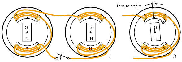
Synchronous motor running in step with alternator.
If more torque in the direction of rotation is applied to the rotor of one of the above rotating alternators, the angle of the rotor will advance (opposite of (3)) with respect to the magnetic field in the stator coils while still synchronized and the rotor will deliver energy to the AC line like an alternator. The rotor will also be advanced with respect to the rotor in the other alternator. If a load such as a brake is applied to one of the above units, the angle of the rotor will lag the stator field as at (3), extracting energy from the AC line, like a motor. If excessive torque or drag is applied, the rotor will exceed the maximum torque angle advancing or lagging so much that synchronization is lost. Torque is developed only when synchronization of the motor is maintained.
In the case of a small synchronous motor in place of the alternator Figure above right, it is not necessary to go through the elaborate synchronization procedure for alternators. However, the synchronous motor is not self starting and must still be brought up to the approximate alternator electrical speed before it will lock (synchronize) to the generator rotational rate. Once up to speed, the synchronous motor will maintain synchronism with the AC power source and develop torque.
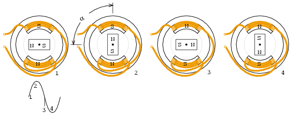
Sinewave drives synchronous motor.
Assuming that the motor is up to synchronous speed, as the sine wave changes to positive in Figure above (1), the lower north coil pushes the north rotor pole, while the upper south coil attracts that rotor north pole. In a similar manner the rotor south pole is repelled by the upper south coil and attracted to the lower north coil. By the time that the sine wave reaches a peak at (2), the torque holding the north pole of the rotor up is at a maximum. This torque decreases as the sine wave decreases to 0 VDC at (3) with the torque at a minimum.
As the sine wave changes to negative between (3&4), the lower south coil pushes the south rotor pole, while attracting rotor north rotor pole. In a similar manner the rotor north pole is repelled by the upper north coil and attracted to the lower south coil. At (4) the sinewave reaches a negative peak with holding torque again at a maximum. As the sine wave changes from negative to 0 VDC to positive, The process repeats for a new cycle of sine wave.
Note, the above figure illustrates the rotor position for a no-load condition (α=0o). In actual practice, loading the rotor will cause the rotor to lag the positions shown by angle α. This angle increases with loading until the maximum motor torque is reached at α=90o electrical. Synchronization and torque are lost beyond this angle.
The current in the coils of a single phase synchronous motor pulsates while alternating polarity. If the permanent magnet rotor speed is close to the frequency of this alternation, it synchronizes to this alternation. Since the coil field pulsates and does not rotate, it is necessary to bring the permanent magnet rotor up to speed with an auxiliary motor. This is a small induction motor similar to those in the next section.
Addition of field poles decreases speed.
A 2-pole (pair of N-S poles) alternator will generate a 60 Hz sine wave when rotated at 3600 rpm (revolutions per minute). The 3600 rpm corresponds to 60 revolutions per second. A similar 2-pole permanent magnet synchronous motor will also rotate at 3600 rpm. A lower speed motor may be constructed by adding more pole pairs. A 4-pole motor would rotate at 1800 rpm, a 12-pole motor at 600 rpm. The style of construction shown (Figure above)) is for illustration. Higher efficiency higher torque multi-pole stator synchronous motors actually have multiple poles in the rotor.
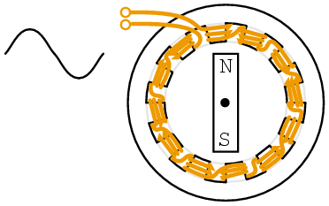
One-winding 12-pole synchronous motor.
Rather than wind 12-coils for a 12-pole motor, wind a single coil with twelve interdigitated steel poles pieces as shown in Figure above. Though the polarity of the coil alternates due to the appplied AC, assume that the top is temporarily north, the bottom south. Pole pieces route the south flux from the bottom and outside of the coil to the top. These 6-souths are interleaved with 6-north tabs bent up from the top of the steel pole piece of the coil. Thus, a permanent magnet rotor bar will encounter 6-pole pairs corresponding to 6-cycles of AC in one physical rotation of the bar magnet. The rotation speed will be 1/6 of the electrical speed of the AC. Rotor speed will be 1/6 of that experienced with a 2-pole synchronous motor. Example: 60 Hz would rotate a 2-pole motor at 3600 rpm, or 600 rpm for a 12-pole motor.
Reprinted by permission of Westclox History at www.clockHistory.com
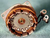
The stator (Figure above) shows a 12-pole Westclox synchronous clock motor. Construction is similar to the previous figure with a single coil. The one coil style of construction is economical for low torque motors. This 600 rpm motor drives reduction gears moving clock hands.
If the Westclox motor were to run at 600 rpm from a 50 Hz power source, how many poles would be required? A 10-pole motor would have 5-pairs of N-S poles. It would rotate at 50/5 = 10 rotations per second or 600 rpm (10 s-1 x 60 s/minute.)
Reprinted by permission of Westclox History at www.clockHistory.com
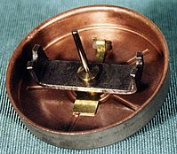
The rotor (Figure above) consists of a permanent magnet bar and a steel induction motor cup. The synchronous motor bar rotating within the pole tabs keeps accurate time. The induction motor cup outside of the bar magnet fits outside and over the tabs for self starting. At one time non-self-starting motors without the induction motor cup were manufactured.
A 3-phase synchronous motor as shown in Figure below generates an electrically rotating field in the stator. Such motors are not self starting if started from a fixed frequency power source such as 50 or 60 Hz as found in an industrial setting. Furthermore, the rotor is not a permanent magnet as shown below for the multi-horsepower (multi-kilowatt) motors used in industry, but an electromagnet. Large industrial synchronous motors are more efficient than induction motors. They are used when constant speed is required. Having a leading power factor, they can correct the AC line for a lagging power factor.
The three phases of stator excitation add vectorially to produce a single resultant magnetic field which rotates f/2n times per second, where f is the power line frequency, 50 or 60 Hz for industrial power line operated motors. The number of poles is n. For rotor speed in rpm, multiply by 60.
   S = f120/n

   where: S = rotor speed in rpm
          f = AC line frequency
          n = number of poles per phase
The 3-phase 4-pole (per phase) synchronous motor (Figure below) will rotate at 1800 rpm with 60 Hz power or 1500 rpm with 50 Hz power. If the coils are energized one at a time in the sequence φ-1, φ-2, φ-3, the rotor should point to the corresponding poles in turn. Since the sine waves actually overlap, the resultant field will rotate, not in steps, but smoothly. For example, when the φ-1 and φ-2 sinewaves coincide, the field will be at a peak pointing between these poles. The bar magnet rotor shown is only appropriate for small motors. The rotor with multiple magnet poles (below right) is used in any efficient motor driving a substantial load. These will be slip ring fed electromagnets in large industrial motors. Large industrial synchronous motors are self started by embedded squirrel cage conductors in the armature, acting like an induction motor. The electromagnetic armature is only energized after the rotor is brought up to near synchronous speed.
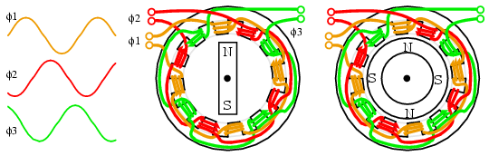
Three phase, 4-pole synchronous motor
Small multi-phase synchronous motors (Figure above) may be started by ramping the drive frequency from zero to the final running frequency. The multi-phase drive signals are generated by electronic circuits, and will be square waves in all but the most demanding applications. Such motors are known as brushless DC motors. True synchronous motors are driven by sine waveforms. Two or three phase drive may be used by supplying the appropriate number of windings in the stator. Only 3-phase is shown above.
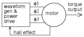
Electronic synchronous motor
The block diagram (Figure above) shows the drive electronics associated with a low voltage (12 VDC) synchronous motor. These motors have a position sensor integrated within the motor, which provides a low level signal with a frequency proportional to the speed of rotation of the motor. The position sensor could be as simple as as solid state magnetic field sensors such as Hall effect devices providing commutation (armature current direction) timing to the drive electronics The position sensor could be a high resolution angular sensor such as a resolver, an inductosyn (magnetic encoder), or an optical encoder.
If constant and accurate speed of rotation is required, (as for a disk drive) a tachometer and phase locked loop may be included. (Figure below) This tachometer signal, a pulse train proportional to motor speed, is fed back to a phase locked loop, which compares the tachometer frequency and phase to a stable reference frequency source such as a crystal oscillator.
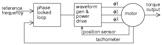
Phase locked loop controls synchronous motor speed.
A motor driven by square waves of current, as provided by simple hall effect sensors, is known as a brushless DC motor. This type of motor has higher ripple torque variation through a shaft revolution than a sine wave driven motor. This is not a problem for many applications. Though, we are primarily interested in synchronous motors in this section.
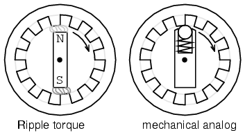
Motor ripple torque and mechanical analog.
Ripple torque, or cogging is caused by magnetic attraction of the rotor poles to the stator pole pieces. (Figure above) Note that there are no stator coils, not even a motor. The PM rotor may be rotated by hand but will encounter attraction to the pole pieces when near them. This is analogous to the mechanical situation. Would ripple torque be a problem for a motor used in a tape player? Yes, we do not want the motor to alternately speed and slow as it moves audio tape past a tape playback head. Would ripple torque be a problem for a fan motor? No.
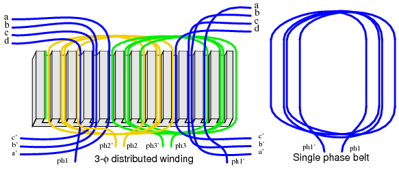
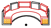
Windings distributed in a belt produce a more sinusoidal field.
If a motor is driven by sinewaves of current synchronous with the motor back emf, it is classified as a synchronous AC motor, regardless of whether the drive waveforms are generated by electronic means. A synchronous motor will generate a sinusoidal back emf if the stator magnetic field has a sinusoidal distribution. It will be more sinusoidal if pole windings are distributed in a belt (Figure above) across many slots instead of concentrated on one large pole (as drawn in most of our simplified illustrations). This arrangement cancels many of the stator field odd harmonics. Slots having fewer windings at the edge of the phase winding may share the space with other phases. Winding belts may take on an alternate concentric form as shown in Figure below.
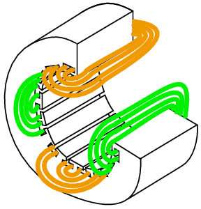
Concentric belts.
For a 2-phase motor, driven by a sinewave, the torque is constant throughout a revolution by the trigonometric identity:
sin2θ + cos2θ = 1
The generation and synchronization of the drive waveform requires a more precise rotor position indication than provided by the hall effect sensors used in brushless DC motors. A resolver, or optical or magnetic encoder provides resolution of hundreds to thousands of parts (pulses) per revolution. A resolver provides analog angular position signals in the form of signals proportional to the sine and cosine of shaft angle. Encoders provide a digital angular position indication in either serial or parallel format. The sine wave drive may actually be from a PWM, Pulse Width Modulator, a high efficiency method of approximating a sinewave with a digital waveform. (Figure below) Each phase requires drive electronics for this wave form phase-shifted by the appropriate amount per phase.
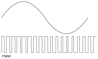
PWM approximates a sinewave.
Synchronous motor efficiency is higher than that of induction motors. The synchronous motor can also be smaller, especially if high energy permanent magnets are used in the rotor. The advent of modern solid state electronics makes it possible to drive these motors at variable speed. Induction motors are mostly used in railway traction. However, a small synchronous motor, which mounts inside a drive wheel, makes it attractive for such applications. The high temperature superconducting version of this motor is one fifth to one third the weight of a copper wound motor.[1] The largest experimental superconducting synchronous motor is capable of driving a naval destroyer class ship. In all these applications the electronic variable speed drive is essential.
The variable speed drive must also reduce the drive voltage at low speed due to decreased inductive reactance at lower frequency. To develop maximum torque, the rotor needs to lag the stator field direction by 90o. Any more, it loses synchronization. Much less results in reduced torque. Thus, the position of the rotor needs to be known accurately. And the position of the rotor with respect to the stator field needs to be calculated, and controlled. This type of control is known as vector phase control. It is implemented with a fast microprocessor driving a pulse width modulator for the stator phases.
The stator of a synchronous motor is the same as that of the more popular induction motor. As a result the industrial grade electronic speed control used with induction motors is also applicable to large industrial synchronous motors.
If the rotor and stator of a conventional rotary synchronous motor are unrolled, a synchronous linear motor results. This type of motor is applied to precise high speed linear positioning.[2]
A larger version of the linear synchronous motor with a movable carriage containing high energy NdBFe permanent magnets is being developed to launch aircraft from naval aircraft carriers.[3]


