


Home > Textbooks > Lessons In Electric Circuits > Vol. II - AC > Transmission Lines > A 50-ohm Cable?
Chapter 14: TRANSMISSION LINES
A 50-ohm Cable?
Early in my explorations of electricity, I came across a length of coaxial cable with the label “50 ohms” printed along its outer sheath. (Figure below) Now, coaxial cable is a two-conductor cable made of a single conductor surrounded by a braided wire jacket, with a plastic insulating material separating the two. As such, the outer (braided) conductor completely surrounds the inner (single wire) conductor, the two conductors insulated from each other for the entire length of the cable. This type of cabling is often used to conduct weak (low-amplitude) voltage signals, due to its excellent ability to shield such signals from external interference.
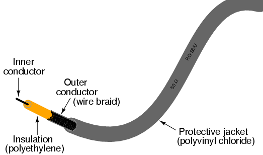
Coaxial cable contruction.
I was mystified by the “50 ohms” label on this coaxial cable. How could two conductors, insulated from each other by a relatively thick layer of plastic, have 50 ohms of resistance between them? Measuring resistance between the outer and inner conductors with my ohmmeter, I found it to be infinite (open-circuit), just as I would have expected from two insulated conductors. Measuring each of the two conductors' resistances from one end of the cable to the other indicated nearly zero ohms of resistance: again, exactly what I would have expected from continuous, unbroken lengths of wire. Nowhere was I able to measure 50 Ω of resistance on this cable, regardless of which points I connected my ohmmeter between.
What I didn't understand at the time was the cable's response to short-duration voltage “pulses” and high-frequency AC signals. Continuous direct current (DC) -- such as that used by my ohmmeter to check the cable's resistance -- shows the two conductors to be completely insulated from each other, with nearly infinite resistance between the two. However, due to the effects of capacitance and inductance distributed along the length of the cable, the cable's response to rapidly-changing voltages is such that it acts as a finite impedance, drawing current proportional to an applied voltage. What we would normally dismiss as being just a pair of wires becomes an important circuit element in the presence of transient and high-frequency AC signals, with characteristic properties all its own. When expressing such properties, we refer to the wire pair as a transmission line.
This chapter explores transmission line behavior. Many transmission line effects do not appear in significant measure in AC circuits of powerline frequency (50 or 60 Hz), or in continuous DC circuits, and so we haven't had to concern ourselves with them in our study of electric circuits thus far. However, in circuits involving high frequencies and/or extremely long cable lengths, the effects are very significant. Practical applications of transmission line effects abound in radio-frequency (“RF”) communication circuitry, including computer networks, and in low-frequency circuits subject to voltage transients (“surges”) such as lightning strikes on power lines.


Related Content:
Video lecture: Transmission Lines - Signal Transmission and Reflection