


Home > Textbooks > Lessons In Electric Circuits > Vol. I - DC > Ohm's Law > Circuit Wiring
Chapter 2: OHM's LAW
Circuit Wiring
So far, we've been analyzing single-battery, single-resistor circuits with no regard for the connecting wires between the components, so long as a complete circuit is formed. Does the wire length or circuit "shape" matter to our calculations? Let's look at a couple of circuit configurations and find out:
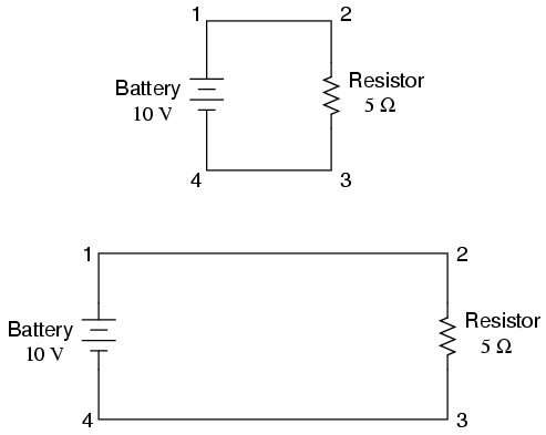
When we draw wires connecting points in a circuit, we usually assume those wires have negligible resistance. As such, they contribute no appreciable effect to the overall resistance of the circuit, and so the only resistance we have to contend with is the resistance in the components. In the above circuits, the only resistance comes from the 5 Ω resistors, so that is all we will consider in our calculations. In real life, metal wires actually do have resistance (and so do power sources!), but those resistances are generally so much smaller than the resistance present in the other circuit components that they can be safely ignored. Exceptions to this rule exist in power system wiring, where even very small amounts of conductor resistance can create significant voltage drops given normal (high) levels of current.
If connecting wire resistance is very little or none, we can regard the connected points in a circuit as being electrically common. That is, points 1 and 2 in the above circuits may be physically joined close together or far apart, and it doesn't matter for any voltage or resistance measurements relative to those points. The same goes for points 3 and 4. It is as if the ends of the resistor were attached directly across the terminals of the battery, so far as our Ohm's Law calculations and voltage measurements are concerned. This is useful to know, because it means you can re-draw a circuit diagram or re-wire a circuit, shortening or lengthening the wires as desired without appreciably impacting the circuit's function. All that matters is that the components attach to each other in the same sequence.
It also means that voltage measurements between sets of "electrically common" points will be the same. That is, the voltage between points 1 and 6 (directly across the battery) will be the same as the voltage between points 3 and 4 (directly across the resistor). Take a close look at the following circuit, and try to determine which points are common to each other:
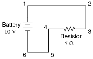
Here, we only have 2 components excluding the wires: the battery and the resistor. Though the connecting wires take a convoluted path in forming a complete circuit, there are several electrically common points in the electrons' path. Points 1, 2, and 3 are all common to each other, because they're directly connected together by wire. The same goes for points 4, 5, and 6.
The voltage between points 1 and 6 is 10 volts, coming straight from the battery. However, since points 5 and 4 are common to 6, and points 2 and 3 common to 1, that same 10 volts also exists between these other pairs of points:
Between points 1 and 4 = 10 volts
Between points 2 and 4 = 10 volts
Between points 3 and 4 = 10 volts (directly across
the resistor)
Between points 1 and 5 = 10 volts
Between points 2 and 5 = 10 volts
Between points 3 and 5 = 10 volts
Between points 1 and 6 = 10 volts (directly across
the battery)
Between points 2 and 6 = 10 volts
Between points 3 and 6 = 10 volts
Since electrically common points are connected together by (zero resistance) wire, there is no significant voltage drop between them regardless of the amount of current conducted from one to the next through that connecting wire. Thus, if we were to read voltages between common points, we should show (practically) zero:
Between points 1 and 2 = 0 volts  Points 1, 2, and
Between points 2 and 3 = 0 volts  3 are electrically
Between points 1 and 3 = 0 volts       common

Between points 4 and 5 = 0 volts  Points 4, 5, and
Between points 5 and 6 = 0 volts  6 are electrically
Between points 4 and 6 = 0 volts      common
This makes sense mathematically, too. With a 10 volt battery and a 5 Ω resistor, the circuit current will be 2 amps. With wire resistance being zero, the voltage drop across any continuous stretch of wire can be determined through Ohm's Law as such:
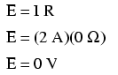
It should be obvious that the calculated voltage drop across any uninterrupted length of wire in a circuit where wire is assumed to have zero resistance will always be zero, no matter what the magnitude of current, since zero multiplied by anything equals zero.
Because common points in a circuit will exhibit the same relative voltage and resistance measurements, wires connecting common points are often labeled with the same designation. This is not to say that the terminal connection points are labeled the same, just the connecting wires. Take this circuit as an example:
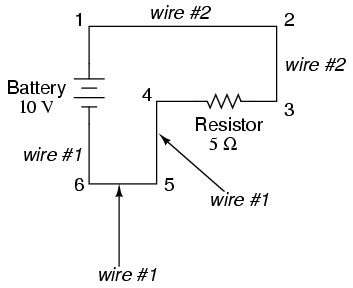
Points 1, 2, and 3 are all common to each other, so the wire connecting point 1 to 2 is labeled the same (wire 2) as the wire connecting point 2 to 3 (wire 2). In a real circuit, the wire stretching from point 1 to 2 may not even be the same color or size as the wire connecting point 2 to 3, but they should bear the exact same label. The same goes for the wires connecting points 6, 5, and 4.
Knowing that electrically common points have zero voltage drop between them is a valuable troubleshooting principle. If I measure for voltage between points in a circuit that are supposed to be common to each other, I should read zero. If, however, I read substantial voltage between those two points, then I know with certainty that they cannot be directly connected together. If those points are supposed to be electrically common but they register otherwise, then I know that there is an "open failure" between those points.
One final note: for most practical purposes, wire conductors can be assumed to possess zero resistance from end to end. In reality, however, there will always be some small amount of resistance encountered along the length of a wire, unless its a superconducting wire. Knowing this, we need to bear in mind that the principles learned here about electrically common points are all valid to a large degree, but not to an absolute degree. That is, the rule that electrically common points are guaranteed to have zero voltage between them is more accurately stated as such: electrically common points will have very little voltage dropped between them. That small, virtually unavoidable trace of resistance found in any piece of connecting wire is bound to create a small voltage across the length of it as current is conducted through. So long as you understand that these rules are based upon ideal conditions, you won't be perplexed when you come across some condition appearing to be an exception to the rule.
- REVIEW:
- Connecting wires in a circuit are assumed to have zero resistance unless otherwise stated.
- Wires in a circuit can be shortened or lengthened without impacting the circuit's function -- all that matters is that the components are attached to one another in the same sequence.
- Points directly connected together in a circuit by zero resistance (wire) are considered to be electrically common.
- Electrically common points, with zero resistance between them, will have zero voltage dropped between them, regardless of the magnitude of current (ideally).
- The voltage or resistance readings referenced between sets of electrically common points will be the same.
- These rules apply to ideal conditions, where connecting wires are assumed to possess absolutely zero resistance. In real life this will probably not be the case, but wire resistances should be low enough so that the general principles stated here still hold.


