


Home > Textbooks > Lessons In Electric Circuits > Vol. I - DC > DC Metering Circuits > Wattmeter Design
Chapter 8: DC METERING CIRCUITS
Wattmeter Design
Power in an electric circuit is the product (multiplication) of voltage and current, so any meter designed to measure power must account for both of these variables.
A special meter movement designed especially for power measurement is called the dynamometer movement, and is similar to a D'Arsonval or Weston movement in that a lightweight coil of wire is attached to the pointer mechanism. However, unlike the D'Arsonval or Weston movement, another (stationary) coil is used instead of a permanent magnet to provide the magnetic field for the moving coil to react against. The moving coil is generally energized by the voltage in the circuit, while the stationary coil is generally energized by the current in the circuit. A dynamometer movement connected in a circuit looks something like this:
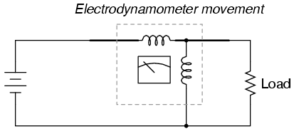
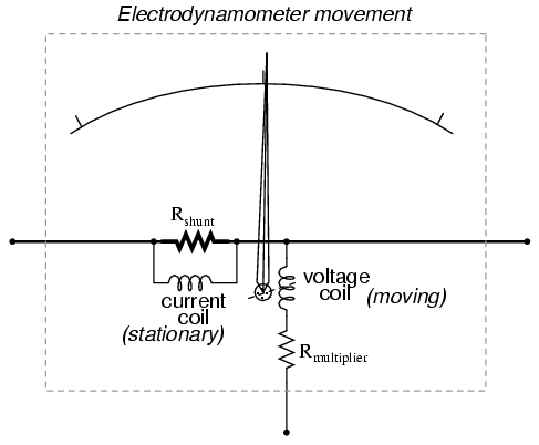
The top (horizontal) coil of wire measures load current while the bottom (vertical) coil measures load voltage. Just like the lightweight moving coils of voltmeter movements, the (moving) voltage coil of a dynamometer is typically connected in series with a range resistor so that full load voltage is not applied to it. Likewise, the (stationary) current coil of a dynamometer may have precision shunt resistors to divide the load current around it. With custom-built dynamometer movements, shunt resistors are less likely to be needed because the stationary coil can be constructed with as heavy of wire as needed without impacting meter response, unlike the moving coil which must be constructed of lightweight wire for minimum inertia.
- REVIEW:
- Wattmeters are often designed around dynamometer meter movements, which employ both voltage and current coils to move a needle.


