


Home > Textbooks > Basic Electronics > AC Network Analysis > Kirchhoff's Laws >
AC Network Analysis
Kirchhoff's Laws
Kirchhoff's laws for AC circuits are as follows:
1. The phasor sum of the currents at any point in the circuit is zero.
2. The phasor sum of the voltages around any closed loop is zero.
The current and voltage equations are derived in the same fashion as those for DC circuits. The algebraic manipulation of phasor quantities is no different from that of DC quantities until numerical quantities are introduced.
When more than one AC voltage source is part of the circuit to be analyzed,
the relative polarities of the sources must be given.
The relative polarity, or sense, of a source is given with respect to its phasor values.
The polarity of voltage can be denoted by "+" and "-" signs or by an arrow pointing from
"+" point to "-" point (similarly as in DC circuits).
Kirchhoff's laws are applied to an AC circuit in Example 1.
Example 1:
Solve the circuit of figure below for the current in each branch
by applying Kirchhoff's laws.
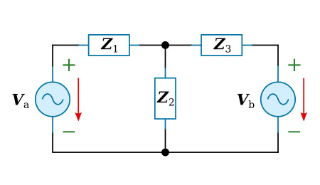

Solution:
1. Arbitrary current directions and voltage polarities are shown in the figure below.
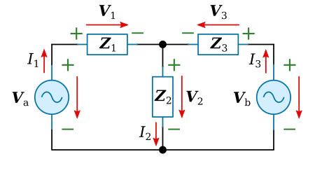
2. A pair of loop equations can now be written with reference to the figure above:

3. A current equation can be written:
![]()
4. Solving the current equation for I1:
![]()
5. Substitute the value of I1 obtained in Step 4 into the first loop equations (Va - V2 - V1 = 0) and solve the resulting equation to obtain I3:

6. Substitute the value of I3 obtained in Step 5 into the second loop equations (Vb - V2 - V3 = 0) and solve the resulting equation to obtain I2:


