Home > Textbooks > Basic Electronics > Other Semiconductor Devices > Power Control Using SCR (Thyristor) >
Other Semiconductor Devices
Power Control Using SCR (Thyristor)
The device used widely for both AC and DC power control is the silicon controlled rectifier (SCR). It has many industrial-electronic applications, such as reversing and speed control for DC motors.
In addition to its anode and cathode, the SCR has a gate. By controlling the phase of the gate signal with respect to the phase of the supply voltage, the firing (delay) angle of the gate can be held to any point in the cycle up to approximately 180°. Through control of the firing angle, the average power delivered to the load can thus be controlled.
With an AC voltage source, the SCR acts as a controlled half-wave rectifier, since it will block both the positive and the negative half-cycles until a positive control signal is applied to the gate. As long as the control signal is present, the SCR will then conduct during the positive half-cycle and block during the negative half-cycle. When the control signal is removed, the SCR will block both half-cycles again, since it automatically turns off at the end of each positive half-cycle. By proper timing of the applied control signal, the SCR can be made to conduct for all or part of the positive half-cycle. Thus, proportioning control of the output, as well as on-off switching, is possible.
DC Power Switch
The input characteristics of the SCR, gate-to-cathode, are similar to the base-emitter input of the NPN silicon transistor. Firing occurs at specific values of input current and voltage. Thus, the device can be used as a static switch with either an AC or DC source.
Circuit below has a DC source, and the SCR acts as a latching switch. Once turned on by a control signal, it will remain on. To turn it off, the anode current must be reduced below the dropout level. Resistor R1 provides a negative-gate bias current and insures a stable "off" condition.
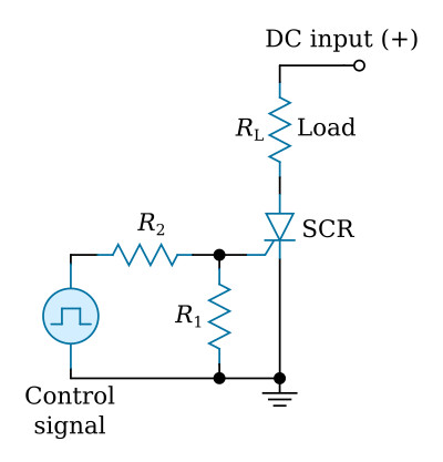
The SCR will latch on at any load current above the dropout level. It will work as well with small loads (e.g. 10 mA) as it does at higher load currents. The circuit can be used as a single-contact latching switch for direct control of a given load, and is useful for driving relay coils or similar electromagnetic loads. With the SCR, an ordinary DC relay can be converted to a high-sensitivity latching relay. For inductive loads a shunt diode may be required, to eliminate a voltage surge when the power is removed.
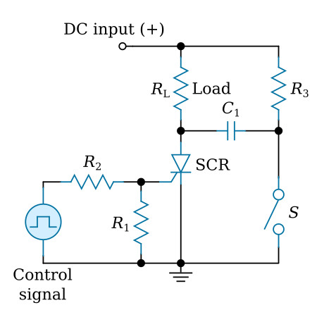
For the simple latching circuit, turn-off can be accomplished by removing the source voltage. The SCR can also be turned off through use of a capacitive shunt, as in circuit below. The SCR is off until an input control signal turns it on. When on, the voltage at the anode is about one volt. C1 charges through R3 to about the value of the supply voltage. Closing the switch causes the charge across the capacitor to drive the SCR anode negative with respect to ground. Load current is no longer supplied by the SCR, but from the discharging capacitor. This method of achieving SCR cutoff is known as shunt-capacitor turn-off. The capacitor must be sufficiently large to hold the SCR anode negative long enough to insure turn-off.
Large amounts of power may also be switched on and off using only small mechanical switches. The ratio of control power to controlled power is so high that a small, light-duty switch (S1, in the figure below) may be used in a circuit which might switch several kilowatts.
In the figure below the SCR is in series with the DC input (supply) and load (RL). Normally it is cut off, so that the load is not energized. When S1 is closed, however, a small current from the positive input terminal, limited by a high resistance R1, flows into the gate and switches the SCR on, energizing the load. Once this action has been initiated, S1, may be opened, but conduction will continue.
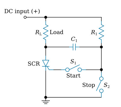
Opening S1, allows capacitor C1 to charge to the DC input voltage, through resistor R1, with its right side positive. When the power is to be switched off, switch S2, is closed momentarily. This connects the positive terminal of the charged capacitor to the negative terminal of the DC input (ground), and a negative voltage is applied to the anode of the rectifier for a brief interval. This cuts the SCR off.
AC Power Switch
SCRs are often used where a large amount of power is to be switched, but the contact current and voltage must be kept low for simple and reliable operation. The SCR provide a solution to this common control problem. The sensitive actuating contacts need supply only the gate firing power, which can be as low as 50 microwatts (1 V, 50 µA). The SCR will directly provide up to 100 watts or more for the output load.
The SCR reverse characteristic is similar to that of a normal silicon rectifier diode, in that both represent essentially open circuits with a negative anode-to-cathode voltage. The forward characteristic is such that it will block the positive anode-to-cathode voltage below a critical breakover voltage if no signal is applied to the gate terminal. However, by exceeding the forward breakover voltage or applying an appropriate gate signal, the device will rapidly switch to a conducting state and present the characteristically low forward voltage drop of a single-junction rectifier.
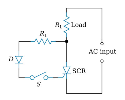
The figure above shows a simple series switch S, which applies an AC signal to the gate. R1 limits this gate current to a safe value, and the diode D prevents the application of inverse voltage between the gate and cathode during the nonconducting cycle. Load RL can be of any value within the limits of the SCR.
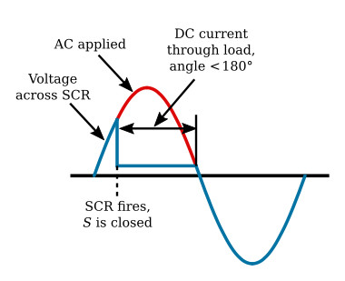
As long as S is open, the SCR will not fire when AC is applied. Closing S allows the positive alternation to cause conduction, since the gate fires the SCR and its anode is positive. As shown in the figure above, the SCR fires for less than 180° and will not fire on the negative alternation. Thus, closing S will control the firing point for each positive alternation, and DC current will flow through the load. The load current can be interrupted by opening S or by the negative anode voltage.
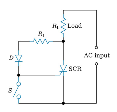
It is possible to use DC on the gate to control the firing point. Or, as in the figure above, the circuit can be fired by opening S where the switch is from the gate to the cathode. The load current can be interrupted by closing S or by the negative anode voltage.

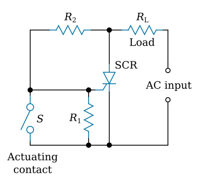
Two other simple arrangements for switching power to loads are shown. The circuit in the figure above will provide load power when the actuating contact is closed, but not when it is open. The circuit in the figure below provides the reverse of this action; power is supplied to the load only when the contact is open. If desired, both circuits can be made to "latch" by operating with DC instead of the AC supply indicated. In the figure above, voltage divider R2, R3 provides the AC gate signal. In the figure below, a closed switch causes the gate and cathode to have the same potential; hence, the SCR will not fire.
AC power may be switched with the circuit shown in the figure below, by means of two SCRs connected back-to-back to handle both half-cycles of the AC voltage.
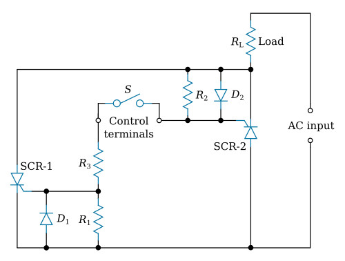
Control current is supplied to the gates through the resistor R3, when the control terminals are short-circuited by an external switch (mechanical or electronic).
The switch which permits each gate to fire may be controlled by an electronic amplifier actuated by light, heat, pressure, etc. When the control switch closes, the SCRs fire once for each alternation. When the switch is open, neither SCR fires. In this way, AC power to the load is controlled.
Half Wave Switch
With an AC voltage source, the SCR performs as a controlled half-wave rectifier, blocking both the positive and the negative half-cycles until a positive control signal is applied to the gate. The SCR will then conduct during the positive half-cycles.
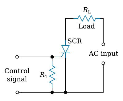
Circuit below is a simple AC static switch which supplies rectified half-wave DC to the load. The input control signal can be AC, DC, or a pulse.
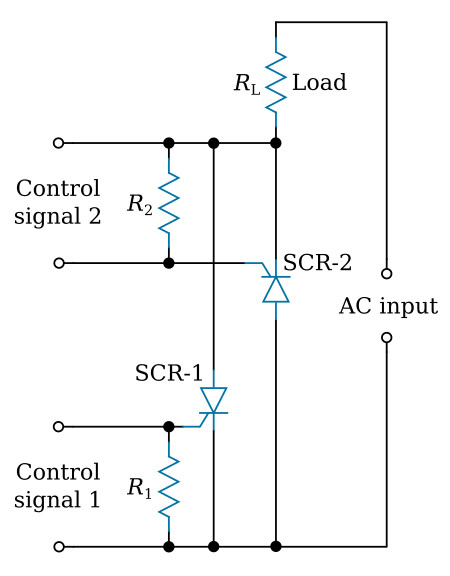
Full Wave Switch
Full-wave static switching is also possible with SCRs. As shown in circuit below, a full-wave circuit can be formed by using two SCR stages. In this circuit, SCRs are connected in inverse parallel and conduct during opposite alternations. Control signal 1 is applied when SCR-1 has a positive anode voltage; during the next alternation, control signal 2 is positive while the anode of SCR-2 is positive.