


Home > Textbooks > Lessons In Electric Circuits > Vol. I - DC > Series-Parallel Combination Circuits > Re-drawing Complex Schematics
Chapter 7: SERIES-PARALLEL COMBINATION CIRCUITS
Re-drawing Complex Schematics
Typically, complex circuits are not arranged in nice, neat, clean schematic diagrams for us to follow. They are often drawn in such a way that makes it difficult to follow which components are in series and which are in parallel with each other. The purpose of this section is to show you a method useful for re-drawing circuit schematics in a neat and orderly fashion. Like the stage-reduction strategy for solving series-parallel combination circuits, it is a method easier demonstrated than described.
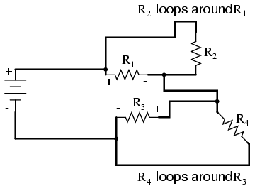
Let's start with the following (convoluted) circuit diagram. Perhaps this diagram was originally drawn this way by a technician or engineer. Perhaps it was sketched as someone traced the wires and connections of a real circuit. In any case, here it is in all its ugliness:
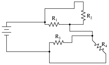
With electric circuits and circuit diagrams, the length and routing of wire connecting components in a circuit matters little. (Actually, in some AC circuits it becomes critical, and very long wire lengths can contribute unwanted resistance to both AC and DC circuits, but in most cases wire length is irrelevant.) What this means for us is that we can lengthen, shrink, and/or bend connecting wires without affecting the operation of our circuit.
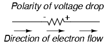
The strategy I have found easiest to apply is to start by tracing the current from one terminal of the battery around to the other terminal, following the loop of components closest to the battery and ignoring all other wires and components for the time being. While tracing the path of the loop, mark each resistor with the appropriate polarity for voltage drop.
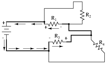
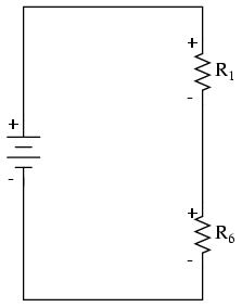
In this case, I'll begin my tracing of this circuit at the negative terminal of the battery and finish at the positive terminal, in the same general direction as the electrons would flow. When tracing this direction, I will mark each resistor with the polarity of negative on the entering side and positive on the exiting side, for that is how the actual polarity will be as electrons (negative in charge) enter and exit a resistor:
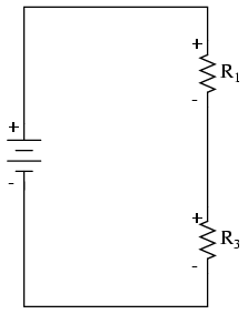
Any components encountered along this short loop are drawn vertically in order:
Now, proceed to trace any loops of components connected around components that were just traced. In this case, there's a loop around R1 formed by R2, and another loop around R3 formed by R4:
Tracing those loops, I draw R2 and R4 in parallel with R1 and R3 (respectively) on the vertical diagram. Noting the polarity of voltage drops across R3 and R1, I mark R4 and R2 likewise:
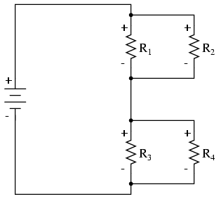
Now we have a circuit that is very easily understood and analyzed. In this case, it is identical to the four-resistor series-parallel configuration we examined earlier in the chapter.
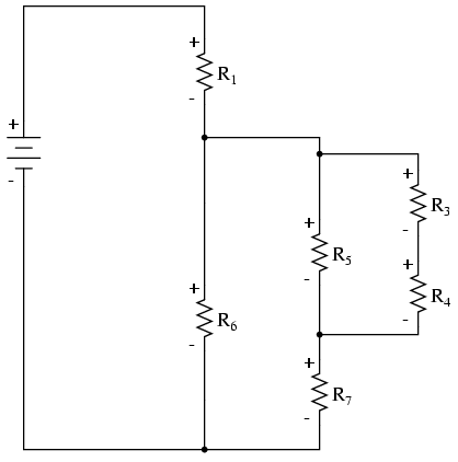
Let's look at another example, even uglier than the one before:
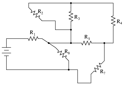
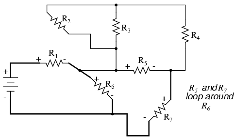
The first loop I'll trace is from the negative (-) side of the battery, through R6, through R1, and back to the positive (+) end of the battery:
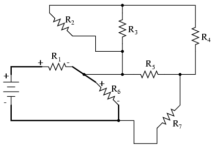
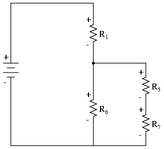
Re-drawing vertically and keeping track of voltage drop polarities along the way, our equivalent circuit starts out looking like this:
Next, we can proceed to follow the next loop around one of the traced resistors (R6), in this case, the loop formed by R5 and R7. As before, we start at the negative end of R6 and proceed to the positive end of R6, marking voltage drop polarities across R7 and R5 as we go:
Now we add the R5--R7 loop to the vertical drawing. Notice how the voltage drop polarities across R7 and R5 correspond with that of R6, and how this is the same as what we found tracing R7 and R5 in the original circuit:
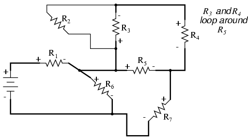
We repeat the process again, identifying and tracing another loop around an already-traced resistor. In this case, the R3--R4 loop around R5 looks like a good loop to trace next:
Adding the R3--R4 loop to the vertical drawing, marking the correct polarities as well:
With only one remaining resistor left to trace, then next step is obvious: trace the loop formed by R2 around R3:
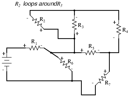
Adding R2 to the vertical drawing, and we're finished! The result is a diagram that's very easy to understand compared to the original:
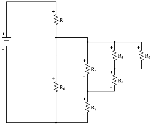
This simplified layout greatly eases the task of determining where to start and how to proceed in reducing the circuit down to a single equivalent (total) resistance. Notice how the circuit has been re-drawn, all we have to do is start from the right-hand side and work our way left, reducing simple-series and simple-parallel resistor combinations one group at a time until we're done.
In this particular case, we would start with the simple parallel combination of R2 and R3, reducing it to a single resistance. Then, we would take that equivalent resistance (R2//R3) and the one in series with it (R4), reducing them to another equivalent resistance (R2//R3--R4). Next, we would proceed to calculate the parallel equivalent of that resistance (R2//R3--R4) with R5, then in series with R7, then in parallel with R6, then in series with R1 to give us a grand total resistance for the circuit as a whole.
From there we could calculate total current from total voltage and total resistance (I=E/R), then "expand" the circuit back into its original form one stage at a time, distributing the appropriate values of voltage and current to the resistances as we go.
- REVIEW:
- Wires in diagrams and in real circuits can be lengthened, shortened, and/or moved without affecting circuit operation.
- To simplify a convoluted circuit schematic, follow these steps:
- Trace current from one side of the battery to the other, following any single path ("loop") to the battery. Sometimes it works better to start with the loop containing the most components, but regardless of the path taken the result will be accurate. Mark polarity of voltage drops across each resistor as you trace the loop. Draw those components you encounter along this loop in a vertical schematic.
- Mark traced components in the original diagram and trace remaining loops of components in the circuit. Use polarity marks across traced components as guides for what connects where. Document new components in loops on the vertical re-draw schematic as well.
- Repeat last step as often as needed until all components in original diagram have been traced.


