


Home > Textbooks > Selected Circuits > Amplifiers > Impedance Matching Line Driver >
Amplifiers
Impedance Matching Line Driver
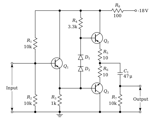
This circuit provides a means of impedance matching between a frequency filter circuit and a low impedance coaxial cable.
The input stage of this circuit is an emitter-follower consisting of transistor Q1, and represents a high input impedance. The output stage is a complementary-symmetry emitter circuit consisting of transistors Q2 and Q3, which are capable of driving a low impedance coaxial cable (90 ohms) terminated in its characteristic impedance without noticeable distortion. Diodes D1 and D2 provide bias for transistors Q2 and Q3, maintaining a voltage difference between the bases of the transistors to eliminate crossover distortion. Transistor Q3 conducts on the positive half of the input sine wave and transistor Q2 conducts on the negative half.
