


Home > Textbooks > Selected Circuits > Power Supplies > Zener-Diode Regulated Power Supply >
Power Supplies
Zener-Diode Regulated Power Supply
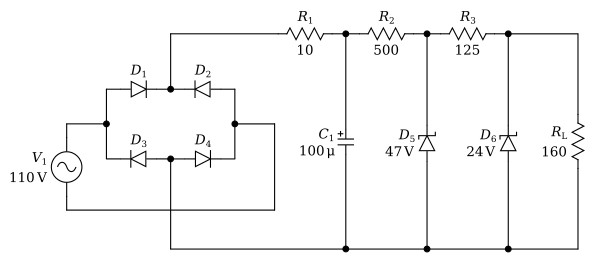
This is an example of a two-stage shunt regulator using Zener diodes. The voltage provided at C1 by the bridge rectifier, comprised of D1 through D4, is about 140 volts (DC) with 10 volts peak to peak ripple. The resistor, R2, and the first Zener diode regulator, D5, provides additional filtering, reducing the DC voltage to 47 volts. The value of the series resistor, R2, was calculated to allow a current of approximately 50 mA (DC) to pass through the first diode, at a nominal input of 120 volts (RMS).
The second regulator provides further ripple reduction while regulating the output at 24 volts for load variations from zero to 150 mA (DC). The output voltage drops about 0.5% when the load is changed from zero to 150 mA (DC).
The circuit will take input fluctuations from 100 to 140 volts with little effect on the output. If lower voltages are expected, the circuit may be designed so that diodes will carry a larger current at 155 volts (RMS) input. The upper limit is imposed by the rating of D5.
