


Home > Textbooks > Selected Circuits > Power Supplies > Full Wave Bridge and Regulator >
Power Supplies
Full Wave Bridge and Regulator
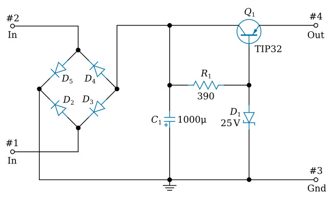
This circuit is a standard full wave rectifier followed by a series regulator. AC power (27 Vrms) is applied to the input pins, #1 and #2. When Pin #2 is positive with respect to Pin #1, the upper left and lower right diodes will conduct (the other two are turned off) and current will flow in such a manner as to charge capacitor C1 so the junction with R1 is negative.
When the input is such that Pin #2 is negative with respect to Pin #1, the upper right and lower left diodes will be conducting while the other two diodes are turned off. Again current will flow in such a manner as to charge C1 in the same direction.
R1 and D1 form a voltage divider across C1. D1 is a Zener diode. When it is placed in a circuit reversed biased (anode to the negative side and cathode to the positive side) it will present a high impedance until the applied voltage reaches the breakdown voltage of the diode. From this point on as the applied voltage increases, the impedance of the diode will change in such a manner as to maintain a constant potential drop across the diode. This maintains a constant voltage at the base of Q1. R1 serves to limit the current through the Zener diode and to drop the excessive voltage.
The collector of Q1 is connected to the negative side of the full wave bridge, the base connected to the constant voltage provided by the Zener diode and the emitter is connected directly to the load which appears across output terminal #4 and ground (terminal #3). Q1 acts as an emitter follower where the load is its emitter resistor.
The constant voltage applied to the base of transistor Q1 tends to hold its emitter at a voltage slightly less, thus the output voltage is held relatively constant at a voltage somewhat less than the Zener reference voltage regardless of changes in the applied input AC.
This simple type of regulator regulates for input voltage changes, but will also provide some regulation for changes in output loads due to their effects on the voltage appearing across C1. Circuit regulation will maintain the output voltage from zero to the full load of 1 A at about ±0.5 V.
