


Home > Textbooks > Selected Circuits > Power Supplies > 150-Volt Series Regulator >
Power Supplies
150-Volt Series Regulator
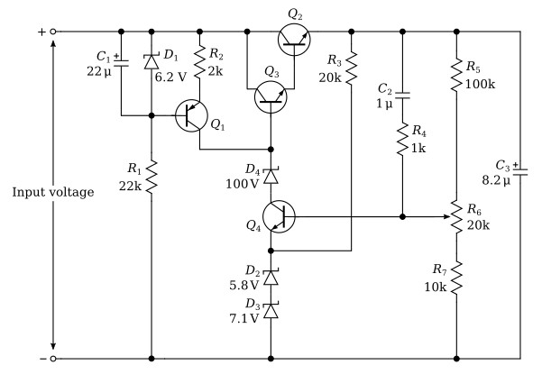
A regulator capable of delivering 100 mA (DC) to a 150-volt load is shown above. This regulator was designed for use with choke-input-filter rectifier system which is not shown but which produces about 170 volts to the input of the regulator. The output voltage is sensed by the voltage divider comprised of R5, R6, and R7, and is compared with the voltage reference by Q4. The voltage reference of about 12.9 volts is developed by two Zener diodes in series, D2 and D3, which were chosen to produce a voltage temperature coefficient which would tend to compensate for the change in VBE in Q4 with temperature.
The output load for the collector of Q4 is about 138 volts from the emitter of Q4 so that voltage breakdown and high dissipation could be a severe problem with Q4. Both problems are solved by the use of D4, a 100-volt Zener diode which reduces both the voltage and dissipation in Q4 to manageable levels.
Transistor Q1 is used as a constant-current source of about 2.8 mA (DC) in conjunction with R1, R2, D1 and C1. It provides a high-impedance source of current for both Q3 and Q4 and maximizes the gain available from Q4. Transistor Q3 acts as an emitter follower in transferring the regulating signal from Q4 to the series-regulating transistor, Q2, which also operates as an emitter follower.
The network C2 and R4 is used to stabilize the feedback loop.
