


Home > Textbooks > Selected Circuits > Power Supplies > Current-Limiting Circuit >
Power Supplies
Current-Limiting Circuit
A current-monitoring circuit protects a 28-Vdc power supply against an overload. The current-limiting element in this circuit consists of a pair of power metal oxide/semiconductor field-effect transistors (MOSFET's). By taking advantage of their low "on" resistances and their low required drive powers, one can obtain a circuit that has low insertion resistance and that limits current to the load. To limit the current by use of conventional bipolar transistors, one would have to provide for standby power to ensure the saturation of such transistors to maintain a low voltage drop across them. The use of the MOSFET'S in this circuit reduces the required standby power. The MOSFET's chosen for this circuit are of the P-channel type.
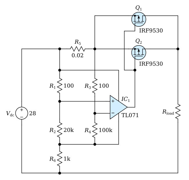
As shown in the figure, the two P-channel power MOSFET's, Q1 and Q2, are connected in parallel to handle the desired maximum current of about 5 A. A small precise wirewound resistor of 0.02 Ω is used to sense the current. The current-sensing voltage developed across this resistor is sensed by the operational amplifier, and compared with a reference voltage developed by the voltage divider of 100 Ω and 20 kΩ. If the current-sensing voltage equals or exceeds the reference voltage, the drive voltage to Q1 and Q2 is increased until the current-sensing voltage equals the reference voltage. This condition of equality corresponds to a load current of approximately 5 A.
When the current is less than the 5-A maximum, Q1 and Q2 are biased "on" and present a low insertion resistance between the source and the load. Because Q1 and Q2 dissipate considerable power in the current-limiting mode, they have to be mounted on a heat sink capable of dissipating this power.
