


Home > Textbooks > Selected Circuits > Power Supplies > Opamp Voltage Regulator >
Power Supplies
Opamp Voltage Regulator
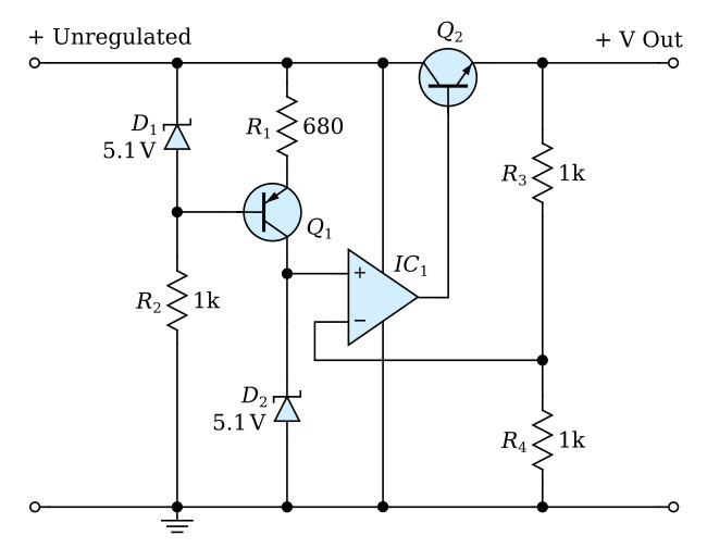
The circuit is indicated schematically in the diagram. A constant current is supplied to the Zener diode D2 by means of transistor Q1 and associated components. The voltage drop across D2 is compared by means of the high-gain operational amplifier IC1 with a similar voltage obtained by means of a voltage divider across the +V output and the ground terminal. The extremely high gain of the amplifier causes the difference between these voltages to be very small, however, any variation between the compared voltages is supplied as an error signal by IC1 to the series transistor Q2. The sense of the error signal is such as to cause the voltage drop across Q2 to decrease if the output voltage becomes lower, or to increase if the output voltage rises.
