


Home > Textbooks > Selected Circuits > Transducers > Temperature Controller for Crystals >
Transducers
Temperature Controller for Crystals
A simple temperature controller for quartz crystal resonators operates on less than 5 W prime power and can heat a crystal from -10°C to +75°C in less than 45 s. Temperature control is accurate to within 0.7°C.
The short time constant of this temperature-controller is due to its reduced mass and smaller separation between the heater and the sensor. Its temperature error is reduced by an exceptionally high-gain circuit.
The unit consists of a heater/sensor crystal assembly and a high-gain control circuit. The nickel-iron wire used as a sensing and heating element has a highly stable resistance-versus-temperature characteristic. The assembly is arranged as an open ring that fits over crystal containers.
A film of room-temperature-vulcanized compound applied between the heater and the container assures good thermal conduction between the two. The heater is tied to the container surface with a lacing cord, and a heat-shrinkable band is placed over the heater as a constrictive cover.
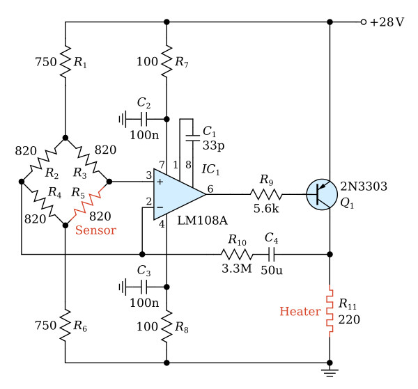
The control circuit incorporates a sensor, an operational amplifier, and a power transistor. The sensor R5 connected to a bridge circuit (R2, R3, R4, and R5) converts the temperature error into voltage error using a 20-mV/°C transfer function developed for this circuit. Resistors R2, R3, and R4 are selected to equal the value of R5 at the desired regulation temperature, and R1 = R6. The latter (R1 and R6) limit current through the bridge to keep the bridge elements from overheating.
The bridge error voltage is applied to an operational amplifier that has a static gain of about 3×10⁵V/V. Resistors R7 and R8 with capacitors C2 and C3 filter the ripple on the prime voltage supply (+28 Vdc), while capacitor C1 is selected to compensate the amplifier according to the manufacturer's specification. In addition, resistor R9 is used to limit base current into transistor Q1 so that full voltage swings of the amplifier output do not drive Q1 into saturation.
