


Home > Textbooks > Selected Circuits > Transducers > Voltage to Pulse Width Converter >
Transducers
Voltage to Pulse Width Converter
Because of availability and low cost, digital proportioning RC servos are frequently used as positioning devices. The circuit below senses the voltage (e.g. from some sensor) and converts it into a pulse width to control the servo and cause it to move in the proper direction. An astable multivibrator with a variable output amplitude controls the output pulse width of a monostable timer whose output is fed to the servo.
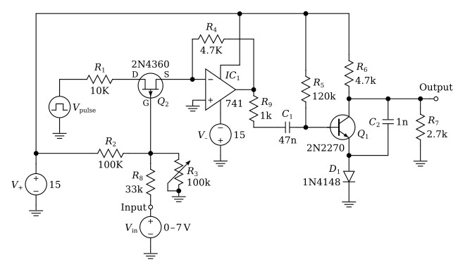
The power supply for the circuit is a standard ± 15-volt source (V+, V–). The input voltage Vin from a sensor is applied to the gate of a P-channel, J-FET (Q2). A pair of bias resistors on the gate of the J-FET set the quiescent operating point. In this circuit, the J-FET is used as a voltage-variable resistor; thus, the voltage applied to the gate will control the pulse amplitude that is passed through the J-FET from the astable multivibrator to the monostable timer. The more positive the voltage applied to the gate of the J-FET, the smaller the pulse amplitude passed by the device.
The astable multivibrator represented by the pulse generator Vpulse operates at a constant frequency of 160 Hz and has an output amplitude of -15 V. This frequency was chosen because of the pulse width requirements of standard servos. The output of the astable multivibrator is fed to an inverting amplifier (IC1) whose gain is controlled by the J-FET. This configuration serves two purposes: first, it isolates the output of the astable multivibrator from the monostable timer, providing a low-impedance output; and second, it inverts the negative pulse that appears at its input so that a positive pulse appears at the output of the amplifier. The positive pulse charges the input capacitor C1 of the monostable timer to a voltage level determined by the control signal on the J-FET. The negative-going transition at the end of the positive pulse places a negative voltage on the base of the timer transistor Q1, which turns it off. The width of the output pulse from this circuit is controlled by the amplitude of the input wave and the time constant of the input capacitor C1 and the resistors R9 and R5.
The output pulse must be positive, about 5 volts, and smoothly variable between a minimum of 1 ms and a maximum of 2 ms for proper control of the servo. The bias adjustment on the gate of the J-FET easily controls the limit on pulse width and assures proper servo control.
