Home > Textbooks > Selected Circuits > Waveform Generators > Voltage-Controlled Oscillator >
Waveform Generators
Voltage-Controlled Oscillator
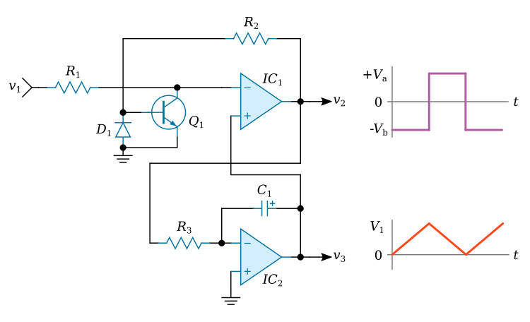
The inverted, voltage-controlled oscillator circuit shown in the figure above contains two operational amplifiers (IC1 and IC2), a switching transistor (Q1), a capacitor (C1), a reverse protection diode (D1) and three resistors (R1, R2, and R3). The control voltage v1 can be varied over some range, typically 0.1 to 10 volts. This voltage is fed through resistor R1 to the inverting input of amplifier IC1. Transistor Q1 in the off state allows voltage v1 to appear at the negative input of IC1 and in the on state Q1 shorts the inverting input of IC1 to common.
The transistor Q1 is controlled by the output of amplifier IC1. When the voltage at the inverting input of IC1 is positive, v2 is negative; when it is negative, v2 is positive. This causes the output of amplifier IC1 to latch in either the positive or the negative state. The output v2 changes state only when the difference voltage between the inputs changes sign. This sign change is caused by the second amplifier IC2. Amplifier IC2 is used as an integrator, with the integration rate controlled by the level of v2. The output, v3, of this integrator is fed to the positive input of IC1. The circuit will now oscillate with the waveforms shown.
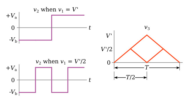
The relationship between the input voltage and the output frequency may be seen in the figure below. The graph v3 shows the output of the integrator as a function of time. Note that the large triangular wave and the small triangular wave have the same slopes. With this in mind, assume that v1 is equal to V' volts. The integrator will integrate between 0 and +V' volts and will cycle over a period T. Now if v1 is reduced to V'/2, the period T is reduced by one-half. Thus the period of oscillation is directly proportional to the input voltage v1; and since the reciprocal of the frequency is equal to the period, v1 must be inversely proportional to the frequency. Graph v2 shows the same relationship for voltage v2.