


Home > Textbooks > Selected Circuits > Waveform Generators > Linear Ramp Voltage >
Waveform Generators
Linear Ramp Voltage
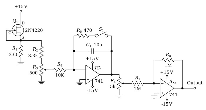
The linear ramp circuit produces a voltage signal that steadily increases from zero at the rate of 25 volts per minute times the Ramp Rate dial setting. The Ramp Rate dial is a 10-turn potentiometer; therefore, if the dial is set to 4.0 turns (from the ground), the ramp rate is 25 V/min × 4.0/10 = 10 V/min.
The FET (field effect transistor), Q1 is connected as a 3 mA constant current source. The current produces 0.9 V across the 330-ohm resistor (R1).
The 3.3-kΩ resistor (R2) reduces this voltage to 0.12 V across trimpot R3. The trimmer is adjusted for proper calibration of the Ramp Rate dial. The output voltage from the trimmer (approximately +42 mV) is integrated by an inverting integrator IC1. The output voltage from the integrator linearly decreases with a constant rate of change of voltage of minus 0.42 volts per second (-25 V/min). S1 in the feedback circuit is used to reset the integrator to zero by discharging the 10μF integrating capacitor through the 470-Ω resistor. A 10-turn potentiometer (Ramp Rate dial R6) is used to adjust the ramped voltage rate from zero to -25 V/min.
IC2 is connected in a unity gain, inverting configuration. This amplifier isolates the Ramp Rate potentiometer to maintain dial linearity and inverts the signal to provide a positive ramped voltage signal. Its output starts at zero and increases (goes positive) at the preset ramp rate.
Useful links:
2N4220 datasheet (pdf)
JFET constant-current source
