


Home > Textbooks > Basic Electronics > Power Sources > Current Source >
Power Sources
Current Source
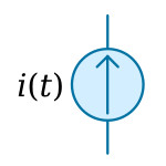
The ideal current source is a device producing a current i(t) that is independent of the voltage across the source terminals. This means that the source current remains i(t) regardless of what is connected across the source terminals. If i(t) is a constant, the source is referred to as the constant-current source.
If there is a resistance R across the source terminals, then a voltage (Ri) will appear. This voltage will become larger for larger values of R because the current remains independent of R. With increasing R the power delivered by the current source increases, and it would become infinite if R were infinite. This is an unreasonable situation, which means that a current source must not be open circuited. The current source is idle when short-circuited because the voltage across its terminals is zero and no power is supplied by the source. The concept of the ideal current source implies that it must have zero internal conductance.
A current source is symbolized by a circle with i(t) written alongside (see the figure below). The reference for the current is indicated by an arrow either alongside or inside the circle, as shown in the figure.
Current Regulators
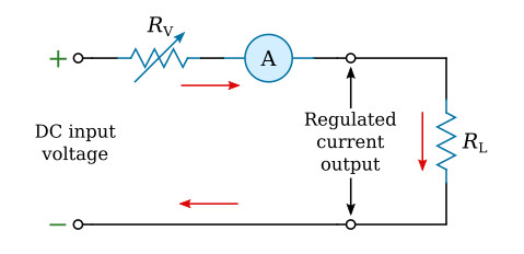
The circuitry which provides a constant current output is called a constant current regulator or just current regulator. The schematic shown in the figure below is a simplified schematic for a current regulator. The variable resistor shown on the schematic is used to illustrate the concept of current regulation. Notice that an ammeter has been included in this circuit to indicate that the circuit shown is that of a current regulator. When the circuit functions properly, the current reading of the ammeter remains constant. In this case the variable resistor (RV) compensates for changes in the load (RL) or DC input voltage. Any increase in load resistance causes a drop in current. To maintain a constant current flow, the resistance of RV must be reduced whenever the load resistance increases. This causes the total resistance to remain constant. An increase in the input voltage must be compensated for by an increase in the resistance of RV, thereby maintaining a constant current flow.
Since use of a variable resistor is not a practical way to control current fluctuation or variation, a transistor and a Zener diode, together with necessary resistors, are used (see below). The Zener diode provides a constant reference voltage. The resistor R1 is connected in series with the load and senses any current changes in the load. The purpose of R2 is to function as a current-limiting resistor for the Zener diode.
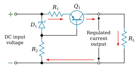
Let's examine in detail how the various components work to maintain the constant current output. A decrease in load resistance causes a corresponding increase in current flow. This results in a larger voltage drop across R1 because of the increased current flow. The voltage drop across D1 remains constant. Because of the increased voltage drop across R1, the forward bias of Q1 has decreased, and the resistance of the transistor increases. Thus, the total resistance around the outside loop of the circuit remains constant. Since the circuit is a current regulator, the output voltage will vary as the regulator maintains a constant current output.
JFET constant-current source
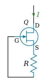
A constant-current source can be formed from a JFET (see the figure above). This configuration is sometimes referred to as a constant-current diode. The voltage at the source of JFET (VS) is automatically maintained near the pinch-off voltage and

As the supply (drain) voltage increases or decreases, the on resistance, rDS, of JFET changes accordingly, thus maintaining I at a nearly constant value.


