


Home > Textbooks > Basic Electronics > Power Sources > Overload Protection >
Power Sources
Overload Protection
Overload protection is very important in voltage regulator design. The regulating element must not be damaged by any expected or unexpected overload or transient.
Fuses are frequently used for protection, but it is always a race between the fuse and regulating element to be first to melt during a heavy overload. Fuses are probably not the best protection and possibly are not even adequate protection in many cases.
The output lead may be interrupted by a magnetic circuit breaker which may be faster than a fuse and consequently safer. An even faster breaker may be made from a flip-flop which is triggered by an excessive load current flowing through a monitoring resistor. The flip-flop can be made to bias off the regulating element in a matter of microseconds so that protection is excellent. A manual reset, or automatic reset after a pause, may be used to restore the flip-flop.
There is a question as to the suitability of circuit interrupters for power supply protection. If a supply with such protection is momentarily overloaded or shorted, its output will drop to zero and remain there until the fuse is replaced or the breaker is reset. For example, if this supply had been supplying a bias voltage for a large transistor installation, conceivably hundreds of transistors could have failed during this brief interval without bias.
Possibly better protection can be afforded the equipment supplied by using a current-limiter method of protection. In this method, constant-voltage operation is maintained up to 100% of rated current, but beyond that limit the voltage regulation may turn into a form of current regulation so that even a short circuit will not draw more than about 120% of rated current. A momentary short will then drop the voltage, but it will restore as quickly as the short is removed. In this way, the load is given the best continuity of power and the least chance of catastrophic damage.
Current-limiting may be done in a number of ways. One obvious way is to place a regulating transformer at the input to the power supply. When this type of transformer is overloaded, its output voltage will drop toward zero and limit the current it will supply. Another method limits the base drive current available for the series power transistor and thereby limits the current it will pass.
One of the best current-limiting schemes places a monitoring resistor in series with the output current in such a way that an excessive current will give rise to a voltage across it which exceeds a preset threshold. When the threshold is exceeded, the monitoring resistor voltage assumes control of the regulating element so that the output current, rather than the voltage, is regulated. When the current demand at the output drops to normal values, the regulating element is again returned to its normal voltage regulation function.
Overloads having nothing to do with output circuit malfunction can occur during turn-on when the output capacitor must be charged to the operating output voltage. This surge current will be controlled by a current-limiter, but if this means of protection is not used, some method of either charging the capacitor slowly so that its surge current is small, or of paralyzing the overload by interrupting circuit when this turn-on surge is expected, will be required.
Basic Limiter
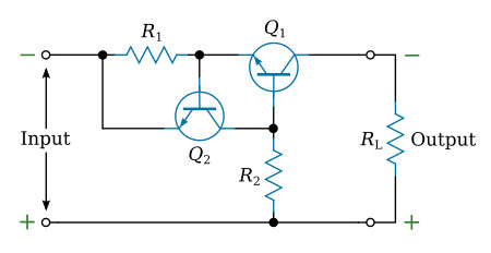
The purpose of this circuit is to limit excessive currents, for example during power turn-on of DC sources. A monitoring resistor is placed in series with the output current.
When a voltage is applied at the input terminals, current builds up through the Q1 collector, and the voltage across R1 (monitoring resistor) increases until the base-to-emitter state of Q2 becomes forward biased at approximately 0.7 volts. As transistor Q2 turns on, the base current to Q1 is reduced, and Q1 tends to turn off, thus limiting the current that is supplied to the load to approximately

In addition to current limiting capabilities, this circuit has potential application as a solid state relay when peak current limiting is required. This can be accomplished by returning R2 to ground through a low-level switching device such as a transistor or relay.


