


Home > Textbooks > Basic Electronics > Power Sources > The Basic Power Supply >
Power Sources
The Basic Power Supply
View A of the figure below shows the block diagram of a basic power supply. Many power supplies are made up of four basic sections: a transformer, a rectifier, a filter, and a regulator.
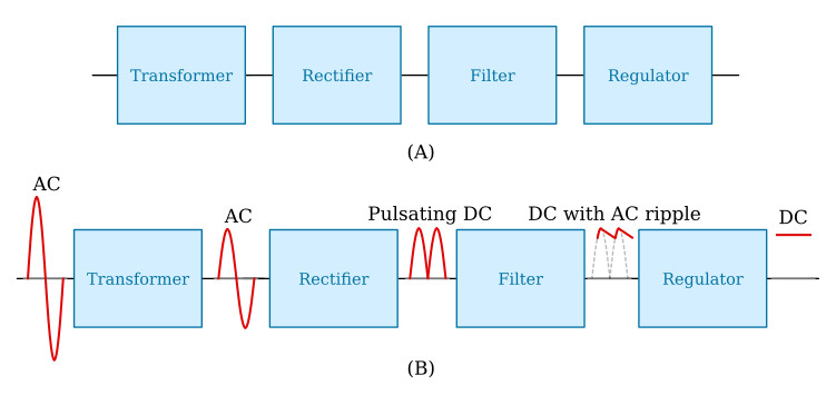
As illustrated in view B of the figure above, the first section is the transformer. The transformer steps up or steps down the input line voltage and isolates the power supply from the power line. The rectifier section converts the alternating current input signal to a pulsating direct current. This pulsating DC is not desirable. For this reason a filter section is used to convert pulsating DC to a purer, more desirable form of DC voltage.
The final section, the regulator, does just what the name implies. It maintains the output of the power supply at a constant level in spite of large changes in load current or input line voltages.
Now that you know what each section does, let's trace an AC signal through the power supply. At this point you need to see how this signal is altered within each section of the power supply. In view B of the figure above, an input line of voltage is applied to the primary of the transformer. The transformer is a step-down transformer with a desirable turns ratio. You can calculate the output for this transformer by multiplying the input voltage by the ratio of the number of turns in the secondary to the number of turns in the primary. Because each diode in the rectifier section conducts for 180 degrees of the 360-degree input, the output of the rectifier will be a pulsating DC. The filter section, a network of resistors, capacitors, or inductors, controls the rise and fall time of the varying signal; consequently, the signal remains at a more constant DC level. The output of the filter is a signal of DC voltage, with AC ripple riding on the DC. The regulator maintains its output at a constant DC level, which is used by the electronic equipment (more commonly called the load). You will see the regulation process more clearly in the discussion of the actual regulator circuits.


