


Home > Textbooks > Solid-State Devices > Special Devices > Silicon Controlled Rectifier >
SPECIAL DEVICES
Silicon Controlled Rectifier
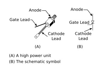
The SILICON CONTROLLED RECTIFIER, usually referred to as an SCR, is one of the family of semiconductors that includes transistors and diodes. A drawing of an SCR and its schematic representation is shown in views A and B of the figure below. Not all SCRs use the casing shown, but this is typical of most of the high-power units.
Although it is not the same as either a diode or a transistor, the SCR combines features of both. Circuits using transistors or rectifier diodes may be greatly improved in some instances through the use of SCRs.
The basic purpose of the SCR is to function as a switch that can turn on or off small or large amounts of power. It performs this function with no moving parts that wear out and no points that require replacing. There can be a tremendous power gain in the SCR; in some units a very small triggering current is able to switch several hundred amperes without exceeding its rated abilities. The SCR can often replace much slower and larger mechanical switches.
The SCR is an extremely fast switch. It is difficult to cycle a mechanical switch several hundred times a minute; yet, some SCRs can be switched 25,000 times a second. It takes just microseconds (millionths of a second) to turn on or off these units. Varying the time that a switch is on as compared to the time that it is off regulates the amount of power flowing through the switch. Since most devices can operate on pulses of power (alternating current is a special form of alternating positive and negative pulse), the SCR can be used readily in control applications. Motor-speed controllers, inverters, remote switching units, controlled rectifiers, circuit overload protectors, latching relays, and computer logic circuits all use the SCR.
The SCR is made up of four layers of semiconductor material arranged PNPN. The construction is shown in view A of the figure below. In function, the SCR has much in common with a diode, but the theory of operation of the SCR is best explained in terms of transistors.
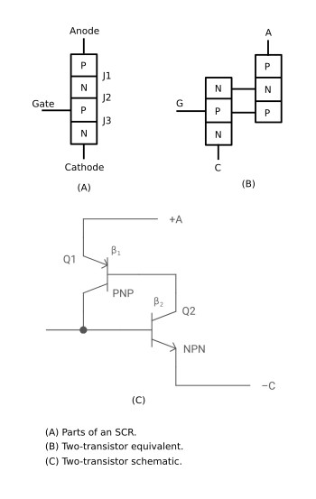
Consider the SCR as a transistor pair, one PNP and the other NPN, connected as shown in views B and C. The anode is attached to the upper P-layer; the cathode, C, is part of the lower N-layer; and the gate terminal, G, goes to the P-layer of the NPN transistor.
In operation the collector of Q2 drives the base of Q1, while the collector of Q1 feeds back to the base of Q2. β1 (Beta) is the current gain of Q1, and β2 is the current gain of Q2. The gain of this positive feedback loop is their product, β1 times β2. When the product is less than one, the circuit is stable; if the product is greater than unity, the circuit is regenerative. A small negative current applied to terminal G will bias the NPN transistor into cutoff, and the loop gain is less than unity.
Under these conditions, the only current that can exist between output terminals A and C is the very small cutoff collector current of the two transistors. For this reason the impedance between A and C is very high.
When a positive current is applied to terminal G, transistor Q2 is biased into conduction, causing its collector current to rise. Since the current gain of Q2 increases with increased collector current, a point (called the breakover point) is reached where the loop gain equals unity and the circuit becomes regenerative. At this point, collector current of the two transistors rapidly increases to a value limited only by the external circuit. Both transistors are driven into saturation, and the impedance between A and C is very low. The positive current applied to terminal G, which served to trigger the self-regenerative action, is no longer required since the collector of PNP transistor Q1 now supplies more than enough current to drive Q2. The circuit will remain on until it is turned off by a reduction in the collector current to a value below mat necessary to maintain conduction.
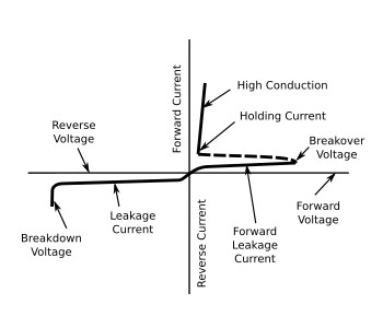
The characteristic curve for the SCR is shown in the figure below. With no gate current, the leakage current remains very small as the forward voltage from cathode to anode is increased until the breakdown point is reached. Here the center junction breaks down, the SCR begins to conduct heavily, and the drop across the SCR becomes very low.
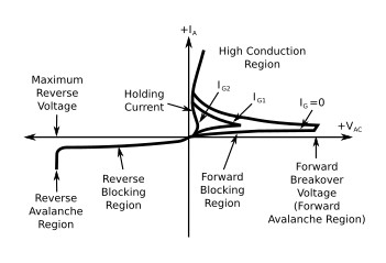
The effect of a gate signal on the firing of an SCR is shown in the figure below. Breakdown of the center junction can be achieved at speeds approaching a microsecond by applying an appropriate signal to the gate lead, while holding the anode voltage constant. After breakdown, the voltage across the device is so low that the current through it from cathode to anode is essentially determined by the load it is feeding.
The important thing to remember is that a small current from gate to cathode can fire or trigger the SCR, changing it from practically an open circuit to a short circuit. The only way to change it back again (to commutate it) is to reduce the load current to a value less than the minimum forward-bias current. Gate current is required only until the anode current has completely built up to a point sufficient to sustain conduction (about 5 microseconds in resistive-load circuits). After conduction from cathode to anode begins, removing the gate current has no effect.
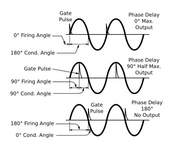
The applications of the SCR as a rectifier are many. In fact, its many applications as a rectifier give this semiconductor device its name. When alternating current is applied to a rectifier, only the positive or negative halves of the sine waves flow through. All of each positive or negative half cycle appears in the output. When an SCR is used, however, the controlled rectifier may be turned on at any time during the half cycle, thus controlling the amount of dc power available from zero to maximum, as shown in the figure below. Since the output is actually dc pulses, suitable filtering can be added if continuous direct current is needed. Thus any dc operated device can have controlled amounts of power applied to it. Notice that the SCR must be turned on at the desired time for each cycle.
When an ac power source is used, the SCR is turned off automatically, since current and voltage drop to zero every half cycle. By using one SCR on positive alternations and one on negative, full-wave rectification can be accomplished, and control is obtained over the entire sine wave. The SCR serves in this application just as its name implies-as a controlled rectifier of ac voltage.


