


Home > Textbooks > Basic Electronics > Combinational Logic > Binary Adder >
Combinational Logic
Binary Adder
The fundamental operation that computers or other processor devices perform is binary addition. This must be done by units built out of the basic logical building blocks. We will show here some examples of how the basic building blocks can be used to build a binary adder. Binary adders are commonly used as the heart of a computer's arithmetic unit.
Binary Addition
To understand the merits of binary computation, it is important that a few basic number facts or ground rules be established. The number of rules necessary for binary arithmetic is less than that required for decimal computation. Because all numbers are represented by 1's and 0's, only two states are possible for each digit position, instead of ten (0 through 9) as in the decimal system.
The following rules cover all possible situations in binary computation: (1) 1 plus 1 equals 0 plus a carry (the carry is similar to the 1 carried to the next digit position in decimal addition); (2) 1 plus 0 equals 1; (3) 0 plus 0 equals 0.
Let us examine a few typical operations. Assume it is desired to add 6 and 3, using binary numbers.

It should be recalled that the 1's and 0's in a binary number tell whether or not the corresponding powers of 2 are included in the number. The binary number 0110 means

Following through the above addition, adding 6 and 3, proceeding from right to left in normal fashion, we find: 1 plus 0 equals 1; 1 plus 1 equals 0 with a carry, which we mentally place in the third column from the right; in the third column we now have 1 plus 0, which is 1, plus the carry 1, which in turn produces 0 with a carry for the fourth column; in the fourth column we have 0 plus 0, which is 0 plus a carry 1, producing a 1.
Regardless of the size of the number, these simple rules permit rapid addition of binary numbers. The binary version may seem more complicated, but it should be recognized that the binary sum is obtained using only three basic rules. It is much simpler electronically to implement binary addition than decimal addition. Binary addition is much faster when it is performed electronically. As a result, binary coding, or a modification of binary coding, is used in most modern computers.
Binary adders are classified according to their ability to accept and combine the digits. In this section we will discuss quarter adders, half adders, and full adders.
Quarter Adder
A quarter adder is a circuit that can add two binary digits but will not produce a carry. So the quarter adder do half the job of a half adder (although the quarter adder could be truly described as one that provides the sum of two bits). The quarter adder should produce the following results:

You should notice that the output produced is the same as the output for the truth table of an XOR gate. Therefore, an XOR can be used as a quarter adder.
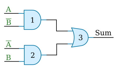
The combination of gates shown in the figure below will also produce the desired results. When A and B are both 0, the output of each AND gate is 0; therefore, the output of the OR gate is 0. When A is 1 and B is 0, then B is 1 and AND gate 1 produces an output of 1, resulting in a sum of 1 at gate 3. With A at 0 and B at 1, gate 2 output is 1, and the sum is 1. When both A and B are high, neither AND gate has an output, and the output of gate 3 is 0. No carry is produced.
Half Adder
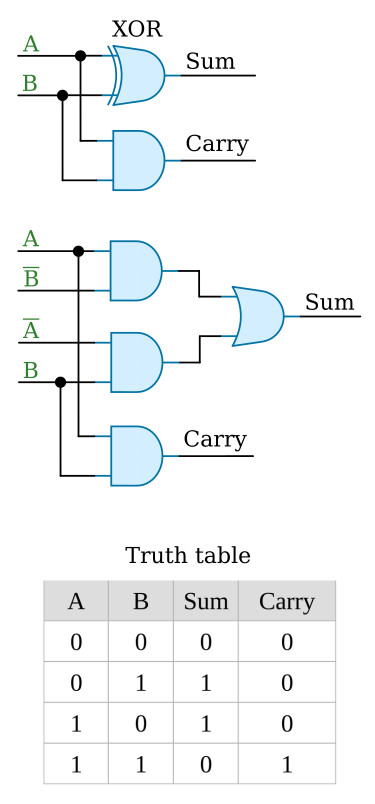
A half adder is designed to combine two binary digits and produce a carry. The figure below shows two ways to construct a half adder. An AND gate is added in parallel to the quarter adder to generate the carry. The SUM column of the truth table represents the output of the quarter adder, and the CARRY column represents the output of the AND gate. We have seen that the output of the quarter adder is 1 when either input, but not both, is 1. It is only when both inputs are 1 that the AND gate is activated and a carry is produced. The largest sum that can be obtained from a half adder is 1 + 1 = 102.
Full Adder
The full adder becomes necessary when a carry input must be added to the two binary digits to obtain the correct sum. A half adder has no input for carries from previous circuits.
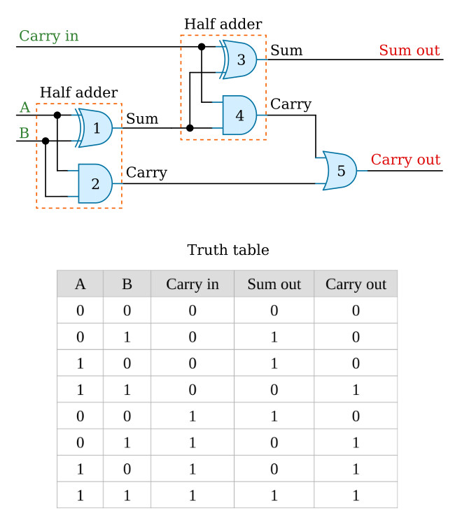
One method of constructing a full adder is to use two half adders and an OR gate as shown in the figure below. The inputs A and B are applied to gates 1 and 2. These make up one half adder. The sum output of this half adder and the carry from a previous circuit become the inputs to the second half adder. The carry from each half adder is applied to gate 5 to produce the carry out for the circuit.
Now let's add a series of numbers and see how the circuit operates.
First, let's add 1 and 0. When either A or B is 1, gate 1 has an output. This output is applied to gates 3 and 4. Since the carry in is 0, only gate 3 will produce an output. The sum of 1 and 0 is 12.
Now let's add 1 and 1. If A and B are both 1s, the output of gate 1 is 0. Since the carry in is 0, the output of gate 3 is 0. Gate 2 produces an output that is applied to gate 5, which produces the carry out. The sum of 1 and 1 is 102, just as it was for the half adder.
When A and B are both 0 and we have a carry in of 1, only gate 3 has an output and produces a sum of 12 with no carry out.
Now, let's add A or B and a carry in. For example, let's assume that A is 1 and B is 0. With these conditions, gate 1 will have an output. This output and the carry in applied to gates 3 and 4 will produce a sum of 0 and a carry of 1. This carry from gate 4 will produce a carry out at gate 5. The sum of A and a carry (1 + 1) equals 102.
When A, B, and the carry in are all 1s, a sum of 1 and a carry out are produced. First, consider A and B. When both are 1, the output of gate 1 is 0, and the output of gate 2 is 1, giving us a carry out at gate 5. The carry in produces a 1 output at gate 3, giving us a sum of 1. The output of the full adder is 112. The sum of 1 + 1 + 1 = 112.
N-bit Binary Adders
The adders discussed in the previous section have been limited to adding single-digit binary numbers and carries. The largest sum that can be obtained using a full adder is 112. N-bit binary adders let us add multiple-digit numbers. If we place full adders in cascade, we can add two- or four-digit numbers or any other size desired.
The figure below uses general symbols to show a cascaded adder capable of adding two, three-digit (3-bit) binary numbers. In previous discussions we have depicted circuits with individual logic gates shown. General symbols (blocks) allow us to analyze circuits with inputs and outputs only. One general symbol may actually contain many and various types of gates and circuits.
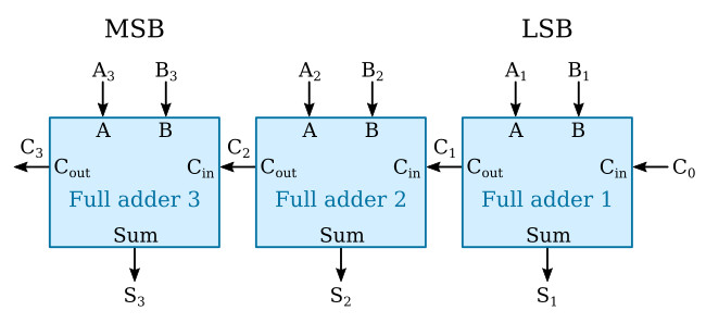
Cascaded adders may be expanded by combining more full adders to accommodate the number of digits (bits) in the numbers to be added. There must be one full adder for each digit.


