Home > Textbooks > Basic Electronics > Combinational Logic > Multiplexer >
Combinational Logic
Multiplexer
A multiplexer is an electronic logic circuit that allows several inputs to share the same output line. As a multiplexer selects which of several data inputs is to be passed on to the single output, it is sometimes called a data selector.
Multiplexer Applications
Aside from providing an easy way of selecting one of many inputs, the multiplexer has one more useful application. Since all inputs can have input signals at the same time, a storage register can hold all the input bits of a data word. A whole binary word may be shifted into the storage register at the multiplexer input in parallel. Then the data-select counter is incremented, one bit at a time, to enable the input lines. In this fashion, each bit of the data word is present at the output for one clock pulse time. A multiplexer used in this manner converts data from a parallel to a serial format. A multiplexer is useful in parallel-to-serial data conversion.
Since the multiplexer permits many inputs to share the same output line, it may be used to control the transmission of many data lines over the same cable or conductor. This permits economy of space in the design of microcircuitry.
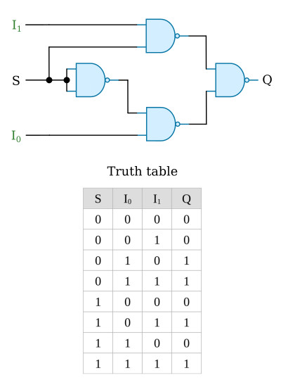
2-Input Multiplexer Using Gates
The circuit below is a simple form of digital multiplexer constructed from NAND gates. It has two data inputs (I0 and I1) and one output (Q). The control input S selects which data input will be passed to the output. When S is logic 0, the multiplexer will pass input I0 to the output. When S is set to logic 1, the multiplexer will pass input I1 to the output.
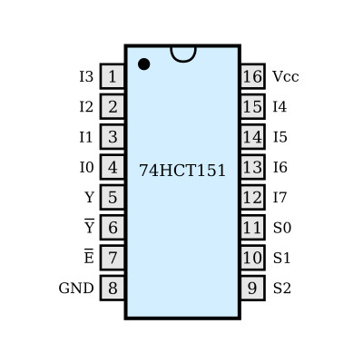
Multiplexers are also available as integrated circuits, for example the 74HCT151 is an 8-input multiplexer and the 74HCT153 is a dual 4-input multiplexer.
74HCT151
This multiplexer utilizes CMOS technology. It possesses high noise immunity, and low power consumption of CMOS with speeds similar to low power Schottky TTL circuits. It has 3 binary select inputs (S0 to S2). If the device is enabled these inputs determine which one of the 8 binary inputs (I0 to I7) will be selected and routed to the output Y. Inverting output (Y) is also available. A HIGH on the enable E input forces the output Y to LOW and output Y to HIGH.