


Home > Textbooks > Basic Electronics > Counters > Ring Counter >
Counters
Ring Counter
A ring counter is defined as a loop of bistable devices (flip-flops) interconnected in such a manner that only one of the devices may be in a specified state at one time. If the specified condition is HIGH, then only one device may be HIGH at one time. As the clock (input) signal is received, the specified state will shift to the next device at a rate of 1 shift per clock.
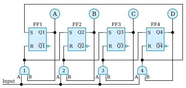
The figure above shows a typical four-stage ring counter. This particular counter is composed of R-S flip-flops. J-K flip-flops may be used as well. Notice that the output of each AND gate is input to the R, or reset side, of the nearest flip-flop and to the S, or set side, of the next flip-flop. The Q output of each flip-flop is applied to the B input of the AND gate that is connected to its own R input.
The circuit input may be normal clock pulses or pulses from elsewhere in the equipment that would indicate some operation has been completed. Now, let’s look at the circuit operation and observe the signal flow as shown in the figure below.
For an initial condition, let’s assume that the output of FF1 is HIGH and that the input and FF2, FF3, and FF4 are LOW. Under these conditions, lamp A will be lit; and lamps B, C, and D will be extinguished. The HIGH from FF1 is also applied to the B input of AND gate 1.
Note: the reset line setting up the initial condition is not shown in the logic diagram above.
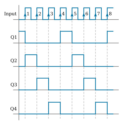
The first input pulse is applied to the A input of each of the AND gates. The B inputs to AND gates 2, 3, and 4 are LOW since the outputs of FF2, FF3, and FF4 are LOW. AND gate 1 now has HIGHs on both inputs and produces a HIGH output. This HIGH simultaneously resets FF1 and sets FF2. Lamp A then goes out, and lamp B goes on. We now have a HIGH on AND gate 2 at the B input. We also have a LOW on AND gate 1 at input B.
Input pulse 2 will produce a HIGH output from AND gate 2 since AND gate 2 is the only one with HIGHs on both inputs. The HIGH from AND gate 2 causes FF2 to reset and FF3 to set. Indicator B goes out and C goes on.
Pulse 3 will cause AND gate 3 to go HIGH. This results in FF3 being reset and FF4 being set. Pulse 4 causes FF4 to reset and FF1 to set, bringing the counter full circle to the initial conditions. As long as the counter is operational, it will continue to light the lamps in sequence A, B, C, D; A, B, C, D, etc.
As we stated at the beginning of this section, only one flip-flop may be in the specified condition at one time. The specified condition shifts one position with each input pulse.


