


Home > Textbooks > Basic Electronics > Counters > Synchronous Counter >
Counters
Synchronous Counter
High-frequency operations require that all the flip-flops of a counter be triggered at the same time to prevent errors. A synchronous counter is used for this type of operation.
The synchronous counter is similar to a ripple counter with two exceptions: The clock pulses are applied to each flip-flop, and additional gates are added to ensure that the flip-flops toggle in the proper sequence.
A logic diagram of a three-stage (modulo-8) synchronous counter is shown in the figure below. The clock input is wired to each of the flip-flops to prevent possible errors in the count. A HIGH is wired to the J and K inputs of FF1 to make the flip-flop toggle. The output of FF1 is wired to the J and K inputs of FF2, one input of the AND gate, and indicator A. The output of FF2 is wired to the other input of the AND gate and indicator B. The AND output is connected to the J and K inputs of FF3. The C indicator is the only output of FF3.
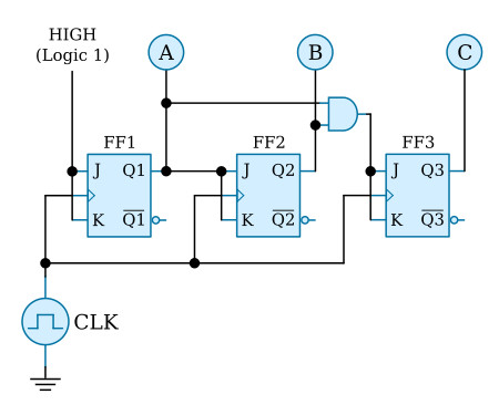
During the explanation of this circuit, you should follow the logic diagram above, and the pulse sequences shown below.
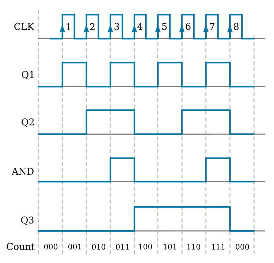
Assume the following initial conditions: The outputs of all flip-flops, the clock, and the AND gate are 0; the J and K inputs to FF1 are HIGH. The positive-going portion of the clock pulse will be used throughout the explanation.
Clock pulse 1 causes FF1 to set. This HIGH lights lamp A, indicating a binary count of 001. The HIGH is also applied to the J and K inputs of FF2 and one input of the AND gate. Notice that FF2 and FF3 are unaffected by the first clock pulse because the J and K inputs were LOW when the clock pulse was applied.
As clock pulse 2 goes HIGH, FF1 resets, turning off lamp A. In turn, FF2 will set, lighting lamp B and showing a count of 0102. The HIGH from FF2 is also felt by the AND gate. The AND gate is not activated at this time because the signal from FF1 is now a LOW. A LOW is present on the J and K inputs of FF3, so it is not toggled by the clock.
Clock pulse 3 toggles FF1 again and lights lamp A. Since the J and K inputs to FF2 were LOW when pulse 3 occurred, FF2 does not toggle but remains set. Lamps A and B are lit, indicating a count of 0112. With both FF1 and FF2 set, HIGHs are input to both inputs of the AND gate, resulting in HIGHs to J and K of FF3. No change occurred in the output of FF3 on clock pulse 3 because the J and K inputs were LOW at the time.
Just before clock pulse 4 occurs, we have the following conditions: FF1 and FF2 are set, and the AND gate is outputting a HIGH to the J and K inputs of FF3. With these conditions all of the flip-flops will toggle with the next clock pulse.
At clock pulse 4, FF1 and FF2 are reset, and FF3 sets. The output of the AND gate goes to 0, and we have a count of 1002. It appears that the clock pulse goes to 1 and the AND output goes to 0 at the same time, but the clock pulse arrives at FF3 before the AND gate goes LOW because of the transit time of the signal through FF1, FF2, and the AND gate.
Between pulses 4 and 8, FF3 remains set because the J and K inputs are LOW. FF1 and FF2 toggle in the same sequence as they did on clock pulses 1, 2, and 3.
Clock pulse 7 results in all of the FFs being set and the AND gate output being HIGH. Clock pulse 8 causes all the FFs to reset and all the lamps to turn off, indicating a count of 0002. The next clock pulse (9) will restart the count sequence.


