


Home > Textbooks > Basic Electronics > Rectifiers > Full-Wave Rectifier >
Rectifiers
Full-Wave Rectifier
A full-wave rectifier is a device that has two or more diodes arranged so that load current flows in the same direction during each half cycle of the AC supply.
The Conventional Full-Wave Rectifier
A diagram of a basic full-wave rectifier is shown in view A of the figure below. The transformer Tr supplies the source voltage for two diode rectifiers, D1 and D2. This transformer has a center-tapped secondary winding that is divided into two equal parts (W1 and W2). W1 provides the source voltage for D1, and W2 provides the source voltage for D2. The voltages at the opposite ends of the secondary windings are 180 degrees out of phase with each other. For example, when the voltage at point B is positive with respect to ground, the voltage at point A is negative with respect to ground. The connections to the diodes are arranged so that the diodes conduct on alternate half cycles. Let's examine the operation of the circuit during one complete cycle.
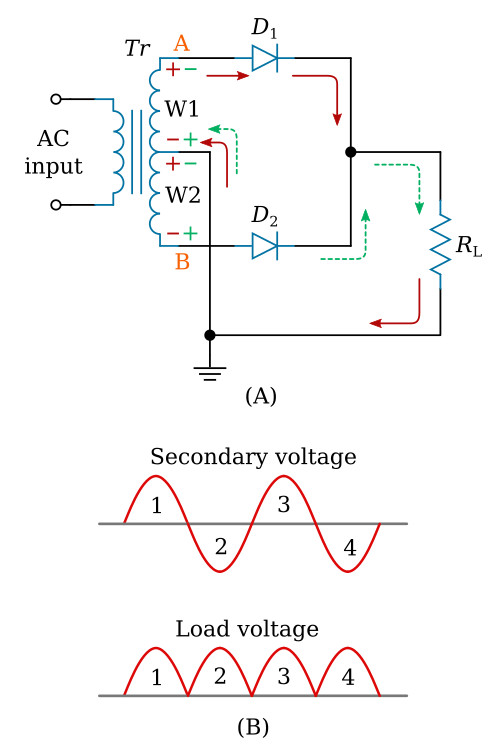
During the first half cycle (indicated by the solid arrows), the voltage at point A is positive with respect to ground, while the voltage at point B is negative with respect to ground. During this alternation, the anode of D2 is driven negative and D2 cannot conduct. For the period of time that the anode of D2 is negative, the anode of D1 is positive, permitting D1 to conduct. As shown, current flows from point A of the transformer, through diode D1, down through the load resistor (RL) to ground (center tap). When D1 conducts, it acts like a closed switch so that the positive half cycle is felt across the load (RL).
During the second half cycle (indicated by the dashed lines), the polarity of the applied voltage has reversed. Now the anode of D2 is positive with respect to ground and the anode of D1 is negative. Now only D2 can conduct. Current now flows, as shown, from point B of the transformer, through diode D2, down through the load resistor (RL) to ground (center tap). Notice that the current flows across the load resistor (RL) in the same direction for both halves of the input cycle.
View B of the figure above represents the output waveform from the full-wave rectifier. The waveform consists of two pulses of current (or voltage) for each cycle of input voltage. The ripple frequency at the output of the full-wave rectifier is therefore twice the line frequency.
The higher frequency at the output of a full-wave rectifier offers a distinct advantage: Because of the higher ripple frequency, the output is closely approximate to pure DC. The higher frequency also makes filtering much easier than it is for the output of the half-wave rectifier.
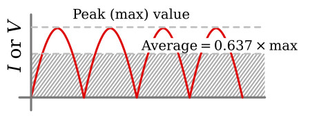
In terms of peak value, the average value of current and voltage at the output of the full-wave rectifier is twice as great as that at the output of the half-wave rectifier. The relationship between the peak value and the average value is illustrated in the figure below. Since the output waveform is essentially a sine wave with both alternations at the same polarity, the average current or voltage is 63.7 percent (or 0.637) of the peak current Ipeak or voltage Vpeak.
As an equation:

Example:
The total voltage across the high-voltage secondary of a
transformer used to supply a full-wave rectifier is 300 volts. Find the average
load voltage (ignore the small voltage drop across the diode).
Solution:
Since the total secondary voltage (VS) is 300 volts, each
diode is supplied one-half of this value, or 150 volts. Because the secondary
voltage is an RMS value, the peak load voltage is:

The average load voltage is:
![]()
Every electric circuit has advantages and disadvantages. The full-wave rectifier is no exception. In studying the full-wave rectifier, you may have found that by doubling the output frequency, the average voltage has doubled, and the resulting signal is much easier to filter because of the high ripple frequency. The only disadvantage is that the peak voltage in the full-wave rectifier is only half the peak voltage in the half-wave rectifier. This is because the secondary of the transformer in the full-wave rectifier is center tapped; therefore, only half the source voltage goes to each diode.
Fortunately, there is a rectifier which produces the same peak voltage as a half-wave rectifier and the same ripple frequency as a full-wave rectifier. This circuit, known as the bridge rectifier, will be the subject of our next discussion.
The Bridge Rectifier
When four diodes are connected as shown in the figure below, the circuit is called a bridge rectifier. The input to the circuit is applied to the diagonally opposite corners of the network, and the output is taken from the remaining two corners.
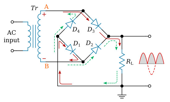
One complete cycle of operation will be discussed to help you understand how this circuit works. Let us assume that there is a positive potential at point A and a negative potential at point B. The positive potential at point A will forward bias D3 and reverse bias D4. The negative potential at point B will forward bias D1 and reverse bias D2. At this time D3 and D1 are forward biased and will allow current flow to pass through them; D4 and D2 are reverse biased and will block current flow. The path for current flow is from point A through D3, down through RL, through D1 to point B. This path is indicated by the solid arrows.
One-half cycle later the polarity across the secondary of the transformer reverses, forward biasing D2 and D4 and reverse biasing D1 and D3. Current flow will now be from point B through D2, down through RL, through D4 to point A. This path is indicated by the broken arrows. You should have noted that the current flow through RL is always in the same direction. In flowing through RL this current develops a voltage corresponding to that shown in the output waveform. Since current flows through the load (RL) during both half cycles of the applied voltage, this bridge rectifier is a full-wave rectifier.
One advantage of a bridge rectifier over a conventional full-wave rectifier is that with a given transformer the bridge rectifier produces a voltage output that is nearly twice that of the conventional full-wave circuit.


