


Home > Textbooks > Basic Electronics > Rectifiers > Half-Wave Rectifier >
Rectifiers
Half-Wave Rectifier
Since a diode will pass current in only one direction, it is ideally suited for converting alternating current (AC) to direct current (DC). When AC voltage is applied to a diode, the diode conducts only on the positive alternation of voltage; that is, when the anode of the diode is positive with respect to the cathode. This simplest type of rectifier is the half-wave rectifier. As shown in view A of the figure below, the half-wave rectifier uses only one diode. During the positive alternation of input voltage, the sine wave applied to the diode makes the anode positive with respect to the cathode. The diode then conducts, and current (I) flows from the top supply lead (the secondary of the transformer), through the diode, and to the bottom supply lead. As indicated by the shaded area of the output waveform in view B, this current exists during the entire period of time that the anode is positive with respect to the cathode (in other words, for the first 180 degrees of the input sine wave).
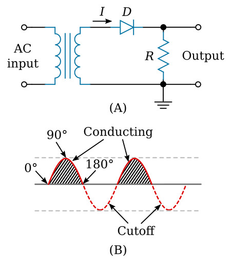
During the negative alternation of input voltage, the anode is driven negative and the diode cannot conduct. When conditions such as these exist, the diode is in cutoff and remains in cutoff for 180 degrees, during which time no current flows in the circuit. The circuit current therefore has the appearance of a series of positive pulses, as illustrated by the shaded areas on the waveform in view B. Notice that although the current is in the form of pulses, the current always flows in the same direction. Current that flows in pulses in the same direction is called pulsating DC. The diode has thus rectified the AC input voltage.
RMS, Peak, and Average Values
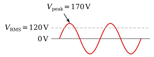
The figure above shows a comparison of the RMS, peak, and average values of the sine waveform associated with the half-wave rectifier. AC voltages are normally specified in terms of their RMS values. Thus, when a 120-volt AC power source is mentioned in this section, it is specifying the RMS value of 120 volts. In terms of peak values
![]()
The peak value is always higher than the RMS value. In fact
![]()
Therefore, if the RMS value is 120 volts, then the peak value must be:
![]()
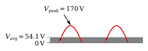
The average value of a sine wave is 0 volts. The figure above shows how the average voltage changes when the negative portion of the sine wave is clipped off. Since the wave form swings positive but never negative (past the "zero-volt" reference line), the average voltage is positive. The average voltage (Vavg) is then determined by the equation:
![]()
Therefore, if the peak value is 170 volts, then the average value must be:
![]()
Ripple Frequency
The half-wave rectifier gets its name from the fact that it conducts during only half the input cycle. Its output is a series of pulses with a frequency that is the same as the input frequency. Thus when operated from a 60-hertz line, the frequency of the pulses is 60 hertz. This is called ripple frequency.


