


Home > Textbooks > Basic Electronics > Relays > Electromechanical Relays >
Relays
Electromechanical Relays
Electromechanical relays which are common to commercial and industrial applications can be generally subdivided into three classifications: general purpose relays, reed relays, and machine control relays. The major difference between these three types of relays is their intended use in a circuit, cost and the life expectancy of the device.
The general purpose relay is a good relay for applications that can use a "throw away", plug-in type relay to simplify troubleshooting and generally keep cost low.
Reed relays are small compact devices with good mechanical features which provide for high reliability. Because of their unique construction, reed relays may be activated in a variety of ways, therefore allowing design circuit application when other relay types would be inappropriate.
The machine tool relay, in contrast to the general purpose relay, is the backbone of control circuitry and is expected to have long life and minimum problems. Machine tool relays provide easy access for contact maintenance and usually provide additional features like time delay and convertible contacts for maximum circuitry flexibility. Machine tool relays are, as expected, more expensive.
The General Purpose Relay
These relays are designed for commercial and industrial application where economy and fast replacement are high priorities. Most general purpose relays have a plug-in feature that makes for quick replacement and simple troubleshooting.
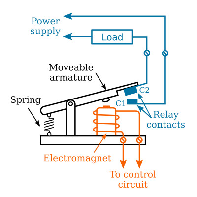
Regardless of its many designs, the general purpose relay is basically a mechanical switch operated by a magnetic coil similar to that of the figure below. In general, a relay consists of a magnetic core and its associated coil (electromagnet), contacts, springs, armature, and the mounting. The figure below illustrates the construction of a relay. When the coil is energized, the flow of current through the coil creates a strong magnetic field which pulls the armature downward to contact C1, completing the circuit from the contact C2 to C1.
The general purpose relay is available in both AC and DC designs. These relays are available with coils that can open or close the contacts from millivolts to the several hundred volt range. Relays with a 6, 12, 24, 48, 115 and 230 volt design are the most common. Today designs offer a number of general purpose relays that require as little as 4 milliamperes at 5 VDC, or 22 milliamperes at 12 VDC, making them IC compatible to TTL and CMOS logic gates. These relays are available in a wide range of switching configurations.
Contact Arrangements
In relays, the use of contacts becomes more complex. To help understand the terminology and complexity of relays, the following information must be understood.
When describing contact arrangements and types, two words are used: "poles" and "throws" (figure below). Pole describes the number of completely isolated circuits that can pass through the switch at one time. Isolated means that maximum rated voltage of the same polarity may be applied to each pole of a given switch without danger of shorting between poles or contacts. A double-pole switch can carry current through two circuits simultaneously, with each circuit isolated from each other. With double-pole switches, the two circuits are mechanically connected so that they open or close at the same time, while still being electrically insulated from each other. This mechanical connection is represented in the symbol by a dashed line connecting the poles together.
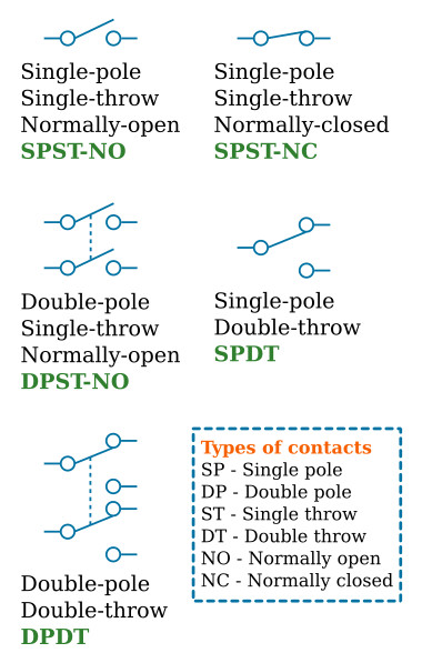
Throws are the number of different closed contact positions per pole that are available on the switch. In other words, throw denotes the total number of different circuits that each individual pole is capable of controlling. The number of throws are independent of the number of poles. It is possible to have a single-throw switch with one or two (or more) poles, as shown in the figure above.
The Reed Relay
The reed relay is a fast operating, single-pole, single-throw switch with normally open (NO) contacts hermetically sealed in a glass envelope. During the sealing operation, dry nitrogen is forced into the tube, creating a clean inner atmosphere for the contacts. Because the contacts are sealed, they are unaffected by dust, humidity and fumes—thus their life expectancy is quite high. Reed relays are designed to be actuated by an external moveable permanent magnet or DC electromagnet. When a magnetic field is brought close to the two flattened reeds sealed in the glass tube, the ferromagnetic (easily magnetized) ends assume opposite magnetic polarity. If the magnetic field is strong enough, the attracting force of the opposing poles overcomes the stiffness of the reed drawing the contacts together. Removing the magnetizing force allows the contacts to spring open. AC electromagnets are not suitable for reed relays since the reed relay switches so fast that it would energize and de-energize on alternate half cycles of a standard 60 Hz (50 Hz) line.
The Reed Contacts
To obtain a low and consistent contact resistance, the overlapping ends of the contacts may be plated with gold, rhodium, silver alloy or other low resistance metals. Contact resistance is often under 0.1 ohm on closing, yet reed contacts have an open contact resistance of several million ohms.
Most reed contacts are capable of direct switching of industrial solenoids, contacts and starters. When interpreting specifications for reed relays, it should be noted that the contact rating indicates the maximum value of current, voltage and volts/amperes rated. Under no circumstances should these values be exceeded.
Actuation of Reed Relays
As mentioned earlier, a permanent magnet is the most common actuator for a reed relay. Permanent magnet actuation can be arranged in several ways dependent upon the switching requirement. Typically, the most often used arrangements are proximity motion, rotation, shielding and biasing method.
The Machine Control Relay
The machine control relay, like the general purpose relay, is merely a mechanical switch controlled by a magnetic coil. This type of relay derives its name from the fact that it is used extensively in machine tools for direct switching of solenoids, contactors and starters. They may also be referred to as heavy duty or industrial control relays.
The popularity of this relay stems from its good quality and reliability, along with its extreme flexibility. In a machine control relay, each contact is a separate removable unit that may be installed to obtain any combination of NO and NC switching. These contacts are also convertible from NO to NC, and vice versa. By merely changing the terminal screws and rotating the unit 180°, the electrician can use the unit as either an NO or NC contact. Relays of one to twelve contact poles are readily assembled from stock parts. The control coils for machine relays are easily changed from one control voltage to another and are available in AC or DC standard ratings. Further, machine relays have available a large number of accessories that may be added to the relay unit. These include indicating lights to monitor the state of the relay contacts, transient suppression to prevent electrical "noise", latching and time controls, to name a few.


