


Home > Textbooks > Basic Electronics > Relays > Solid State Relays >
Relays
Solid State Relays
In the recent decades, the industrial control market has been subject to a massive revolution based on solid state electronics. Due to their declining cost, high reliability and immense capability, solid state devices have begun replacing many devices which operated on mechanical and electromechanical principles.
As with anything new, so with solid state electronics, good judgment must be used when considering its acceptance. Just because solid state is new and appears to have certain advantages, you cannot assume it is best for all applications. Although it can be said that solid state devices will give superior performance in some applications, it is also true that in other applications an electromechanical device will perform better.
In making a choice between solid state and electromechanical, you must compare the electrical, mechanical, and sometimes financial characteristic of each device with the application in which it is to be used. In this portion of the section, we are going to examine the capabilities of solid state relays versus electromechanical relays and explain the difference between these two devices.
Comparison of Electromechanical Relays to Solid State Relays
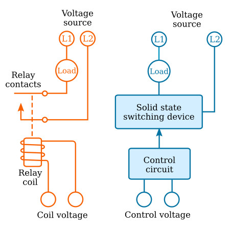
Although both electromechanical relays (EMR) and solid state relays (SSR) are designed to provide a common switching function, each accomplishes the final results in different ways.
Basically, the EMR provides switching through the use of electromagnetic devices and sets of contacts, while the SSR depends upon electronic devices such as silicon controlled rectifiers (SCR), triacs, and MOSFETs to switch without contacts. The figure below illustrates graphically a simple example of both an EMR and SSR with input circuit and load circuit.
Types of Solid State Relays
There are basically four solid state designs which are predominating the control market: direct control, transformer isolation, optical (LED) isolation and hybrid solid state relays. Because each offers similar but distinctly different operating characteristics, each will be discussed.
Direct Control
The figure below shows in block diagram form a direct control or contact closure type of relay for switching AC loads. In this SSR, a set of external switch contacts, connected to the same AC voltage source as the load to be controlled, is used as the control circuit. A triode AC semiconductor (triac), or a pair of back-to-back silicon controlled rectifiers (SCRs), may be used as the load switching device.
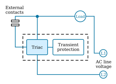
When the switch contacts are closed, the triac conducts and applies AC source voltage to the load. Opening the external contacts turns off the triac and thus removes the AC source voltage from the load. To protect the triac from undesired turn-on due to transient voltage surges, a transient protection network is included.
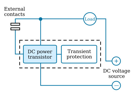
When direct control of a DC load is desired, the solid state relay configuration shown in the figure below is employed. In this circuit, a DC power transistor is used as the electronic switching device. As in the circuit diagram for controlling an AC load (figure above), external switch contacts are used to control the turn-on and turn-off of the power transistor. Alternatively, a second source voltage may be used in place of the external contacts to control the operation of the power transistor. It should be noted that when external contacts are used to control the operation of an SSR, the source voltage appears at the external control contacts. Hence, they must be suitably protected to ensure the safety of the user.
Optically Isolated SSR
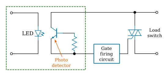
An optically isolated solid state relay is the equivalent of a SPST standard relay. Isolation is provided optically through the use of a light emitting diode (LED) and photo-detector illustrated in the figure below. The LED accepts the relay control voltage and through the LED converts this power to light energy. This light is collected by a photo-detector which controls the triac (or MOSFET) gate-firing circuit. When the control voltage specified is reached, because of sufficient light energy being transmitted to the photo detector, the gate circuit fires. Removal or reduction of control voltage reduces light output and stops triggering the circuit. The DC voltage required to operate the LED may be a specific voltage of, say, 5 VDC, or may fall in a range typically 3 to 32 volts. The characteristics of the LED permit control circuit design that accepts a wide range of input voltages.
Input isolation from output for this type of relay may reach 10 billion ohms. The breakdown voltage is typically 1500 V RMS 50/60Hz. This isolation can be provided only up to a certain point, which is determined by the ratings of the components used. These ratings can be found in the data sheets of most manufacturers. Once these ratings are exceeded, transients can be introduced into the control circuits.
Based on a 10% reduction in light output, the life expectancy of an opto-coupler is in excess of 50,000 hours. It is actuated in microseconds, is not affected by shock or vibration, has no bounce and can be driven directly by either MOS or TTL gates.
The on/off state of the photo detector controls the state of the logic that permits gating of the output triac. Optically coupled designs usually feature zero voltage turn-on of the triac. This means that no matter when the input control voltage is applied, the triac does not turn on until the source voltage is of the order of 15V. This reduces electromagnetic interference at turn-on to less than one-hundredth that of an EMR and approximately one-fifth that of an SSR without zero voltage turn on.
After initial turn-on, successive half cycle turn on for SSRs require 5 to 10 V across the triac, depending on the load being switched. Generally 5 to 15 mA are required to properly operate the coupler. Currents in excess of 20 to 25 mA may start deterioration of the LED coupler, particularly at elevated temperatures.
Transformer Isolation
In many applications, it is desirable or necessary to provide electrical isolation of the control circuit from the load circuit. Isolation is especially necessary when the control circuit is interfaced with low-level logic, due to its susceptibility to transient pulses.
One method of achieving electrical isolation is to use a transformer, as illustrated in the figure below. In this circuit, a DC control voltage is employed to activate the relay. The control voltage is transformed into an AC signal by a solid state oscillator circuit, the output of which provides primary current to a transformer. Oscillator frequency ranges from 50 kHz to 500 kHz. The transformer's output controls the triac gate-firing circuit. Thus, the magnetic coupling of the transformer serves to isolate the control voltage source from the load circuit. An advantage of transformer coupling is that it permits a wide variety of DC control voltage levels to be used. Another advantage is the very low control current required to activate the load.
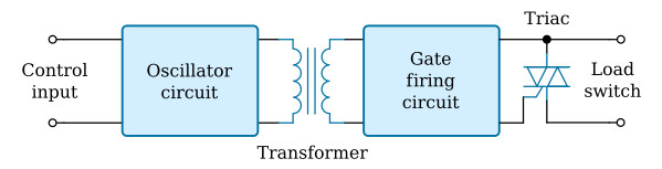
Input-output isolation resistance and breakdown voltage is the same as that of an optoisolator; however, the performance of a transformer coupler does not degrade noticeably over the life of the relay. In addition, the transformer coupled SSR has fewer total components than the opto-isolated SSR and is less temperature sensitive. However, it does not have the zero voltage turn-on feature. A transformer coupled SSR does radiate some electromagnetic interference (EMI) from the oscillator circuit, but it is very minimal and usually is not a problem. The EMI from the triac turning on and off each successive half cycle can produce a higher level EMI than that of the oscillator.
The transient immunity of the transformer coupled SSR is somewhat less than that of the optical coupled SSR.
Hybrid Solid State Relays
Another popular form of SSR is the hybrid solid state relay. Although not a "true" SSR because it incorporates a mechanical component (a reed relay), it essentially operates as a solid state device.
The use of a reed relay does result in some trade-offs in performance, such as slower switching speed, less immunity to shock and vibration, and reduced life because of its mechanical contacts in the input or control stage. The hybrid, however, is compatible with certain TTL logic when sufficient output current is available. Although it requires higher control current values than a true SSR, in addition to having a somewhat longer turn-on time, this hybrid is able to handle higher transient input voltages. A final minor limitation is that the hybrid is more vulnerable to shock and vibration because it incorporates a mechanical component.
The figure below represents a typical hybrid solid state relay incorporating a reed relay in the control circuit. Here the DC control voltage is used to energize a coil which draws the reed relay contacts together. This closes the control circuit, which in turn triggers the triac controller. Electrical isolation in this circuit is provided by the magnetic coupling between the reed relay coil and the reed relay contacts.
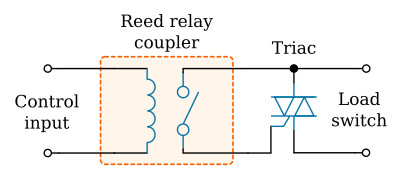
When a reed relay is used as the control portion of a hybrid solid state relay, it is normally operated at a low voltage and current values to provide a relatively long life for the control circuit. On an inductive load application, it is normally the high voltage side of an electromechanical relay that will deteriorate first. A hybrid solid state relay can alleviate that problem by using a triac load controller to provide long life. A second type of hybrid solid state relay employs a solid state device control circuit to energize the coil of a reed only, the contacts of which switch the load circuit. Essentially, this hybrid form is a conventional electromechanical relay with a solid state driver circuit. As such it is subject to many of the same disadvantages as conventional electromechanical relays.
Examples
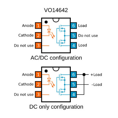
VO14642 MOSFET Relay SPST-NO
Characteristics
DIP-6 package
On-resistance 0.25Ω
Load current 2A DC
Load voltage 60V
Isolation voltage 5300V(RMS)
TTL/CMOS compatible input
Turn-on/Turn-off time < 800µs
Pinout
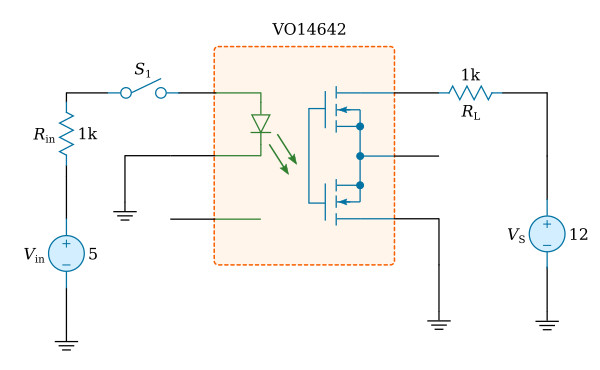
Test circuit
Product information
VO14642 product page
VO14642 datasheet (pdf)
SPICE simulation model


