


Home > Textbooks > Basic Electronics > Transducers > Thermistors >
Transducers
Thermistors
All resistors are temperature sensitive to some extent. Conventional resistors are designed to have the lowest practicable temperature coefficient of resistance, in order that their resistance values may remain constant over a reasonable temperature range. The thermistor, however, is a a type of resistor designed especially for carefully controlled sensitivity to temperature. This special thermally sensitive resistor is useful for temperature sensing in heat-measuring and -detecting instruments, compensation and protection of circuits and components, and other applications in electronic instrumentation and control.
The temperature coefficient of thermistors may be either positive or negative.
NTC (negative temperature coefficient) thermistors have negative
temperature coefficients; that is, as the temperature rises, resistance of
the thermistors decreases, and as the temperature drops, their resistance
increases.
PTC (positive temperature coefficient) thermistors have positive
temperature coefficients. A positive temperature coefficient denotes a rise
in resistance value with a rise in temperature.
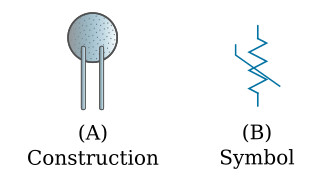
Thermistors are supplied in various sizes and shapes, including beads, rods, discs, and wafers. The simple thermistor is a two-terminal device. In its basic form it consists of two leads embedded on opposite sides of a small, molded form of an appropriately processed mixture of metal oxides. The figure below shows this simplest construction of a thermistor.
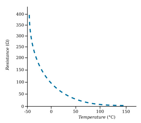
The figure below shows the variation of resistance with temperature in one type of NTC thermistor. When a thermistor is intended to respond to external temperature (as in an electronic thermometer or pyrometer), it must be operated at low current and voltage to minimize self-heating.
At any temperature T, the approximate resistance of a thermistor
![]()
where R0 is its resistance at a reference temperature T0 (sometimes called the "cold temperature"), e = 2.7183, and the exponent k = B (1/T – 1/T0). B is a constant determined by the composition and processing of the semiconductor material. The temperatures and B are expressed in kelvins. The high temperature coefficient and nonlinear resistance of the thermistor make this device a very sensitive temperature detector.
The voltage-current characteristics of a thermistor are important. If the voltage applied to a thermistor is small, the current will be small and no self-heating will occur. When the current in the thermistor is large enough to cause self-heating and raise the temperature of the thermistor appreciably above the ambient temperature, the resistance and current of the thermistor will change.
Self-heating expends a certain amount of power which must be dissipated by the thermistor. In some applications where the thermistor is not employed for temperature sensing, operation at relatively high dissipation levels may be achieved through air cooling or oil immersion of the thermistor.
Thermistor Applications
The next figures show typical applications of thermistors.
Temperature Measurement
The thermistor is a sensitive heat detector and can be made the sensing element in an electrical thermometer or pyrometer. The small bead thermistor may easily be installed in the nose of a temperature probe. Bead and disc thermistors, like thermocouples, may be attached directly to surfaces for the monitoring of temperatures.
The figure below shows three circuits for temperature measurement. In view A the thermistor is connected in series with a constant DC voltage source V, calibration rheostat R, and DC milliammeter. The thermistor resistance, and consequently the meter reading, is a function of temperature.
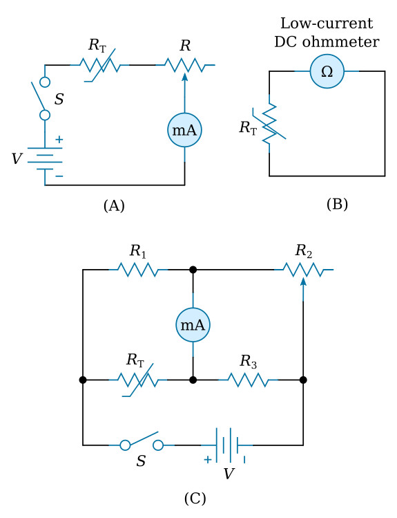
In view B of the figure above an ohmmeter is used to measure the resistance of the thermistor directly. The ohmmeter circuit should pass the smallest practicable current through the thermistor, to minimize self-heating.
In view C of the figure above a resistance bridge circuit has been substituted for the ohmmeter to check the resistance of the thermistor more accurately. At null, the thermistor resistance RT = (R1R3)/R2. For direct reading the dial of R2 may be calibrated in degrees.
Heater Control
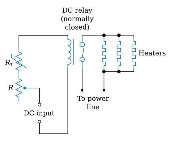
A thermistor may be placed inside an oven or heat chamber to serve as a temperature sensor for automatic control of the heaters.
The figure below shows a control circuit. The NTC thermistor current is adjusted, by means of the sensitivity-control rheostat R, so that the relay is actuated a few tenths of a degree above the desired operating temperature of the oven. This opens the relay contacts and disconnects the heaters. As the temperature drops, the thermistor resistance increases, lowering the current and dropping the relay. This closes the contacts and reconnects the heaters to the power line.
RF Wattmeter
The thermistor can be used for measuring RF (Radio Frequency) power. Its very low reactance permits its use at ultra-high frequencies and microwaves.
The figure below shows a bridge circuit for power measurement. The bridge is balanced initially without RF input, by adjustment of R3. RF energy then is applied to the NTC thermistor through the coupling capacitor C. This energy heats the thermistor, lowering its resistance and unbalancing the bridge. Rheostat R3 then is adjusted to restore null. At this point the hot resistance of the thermistor is RT = (R1R3)/R2. The dial of R3 accordingly may be calibrated for direct readings in watts.
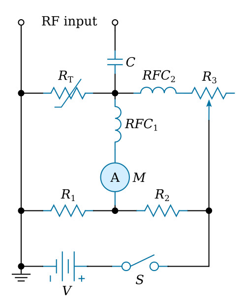
Meter M is a zero-center DC galvanometer or microammeter. The RF chokes RFC1 and RFC2 keep RF energy out of the DC measurement circuit.
Limiter
The nonlinear resistance of the thermistor may be employed in simple circuits for signal limiting, peak compression, and voltage regulation.
The figure below shows a circuit of this type. Resistor R and the NTC thermistor form a voltage divider with the upper output terminal of the circuit connected to the tap between them. The thermistor and resistor are chosen so that, at normal desired output voltage, the thermistor resistance is high. If the input voltage then increases, current I increases and lowers the resistance of the thermistor due to self-heating. This, in effect, reduces the output voltage to its original level. In this way the output voltage is stabilized.
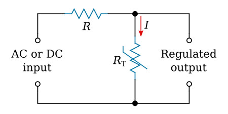
Several of these single stages may be cascaded for increased voltage regulation or signal compression.


