Home > Textbooks > Basic Electronics > Transducers > Linear Variable Differential Transformer (LVDT) >
Transducers
Linear Variable Differential Transformer (LVDT)
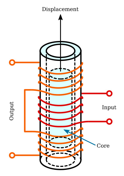
A linear variable differential transformer is a very effective instrument for measuring displacement (position). It is essentially a hollow cylinder (tube) upon which are wound several separate windings. One of these coils serves as the primary winding and two other coils as the secondary windings, the unit constituting a transformer.
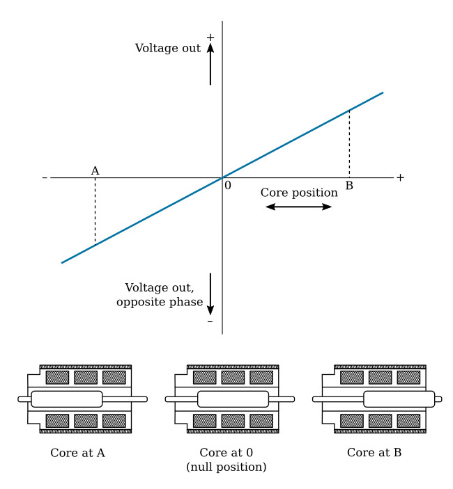
A simple form is shown in the figure below. It has an input of primary winding wound on the center part of a tube, and an output or secondary winding section with half its turns on each end of the tube. The primary winding is excited by an AC supply from an external source. The two secondary windings are wound in opposite directions, so that the EMFs induced in the two secondary windings oppose each other. A ferromagnetic core is located in the center of the tube. The core is movable and may be attached to the displaced element, a diaphragm or seismic mass, for example. Its position determines the flux linkage with each coil. When the core is in the upper position, more flux links with the upper coil than with the lower coil, and the EMF (voltage) output will be a function of the displacement of the core and will have the phase relation of the EMF of the upper coil. Similarly, when the core is in the lower position, more flux links with the lower coil than with the upper coil, and the EMF output will be 180 degrees out of phase with the EMF of the upper coil. When the core is located in the exact center there is a zero output voltage from the secondary windings.
With proper mechanical design the relation between output voltage and displacement can be made linear for a reasonable distance. In the figure below is shown a graph of the output voltage plotted against the core position in a linear variable differential transformer unit. In the diagram of the transformer windings, the primary coil is wound at the center and in between the two secondary coils. In practice, there is never a complete null position, as some residual voltage components are always present which do not cancel.