Home > Textbooks > Basic Electronics > DC Circuits > Introduction >
DC Circuits
Introduction
Electric Circuit
An electric circuit is a collection of individual components (elements) that have been connected by conductive wires. As an example, a bulb connected by conductors across a battery forms a simple electric circuit. In this circuit, electric current will flow from the battery to the bulb.
Electric Current and Voltage
Electric current in a wire is a directed drift of charges (electrons) from one atom to another throughout the length of the wire. The unit of current is the ampere, A. Two conditions are necessary for current to flow: One is wire made of material permitting an easy drift of electrons from atom to atom; the other is a charge difference along the wire from one end to the other.
This difference of charge is called voltage. The unit of voltage is the volt, V. Voltage may be described as the electric pressure that causes current to flow. Voltage is also referred to by many other expressions: pressure, potential, difference of potential, voltage drop, or electromotive force (EMF).
It has been proven that electrons (negative charges) move through a conductor in response to an electric field (voltage). Electron current flow is defined as the directed flow of electrons. The direction of electron movement is from a region of negative potential (e.g. "-" pole of the battery) to a region of positive potential (e.g. "+" pole of the battery).
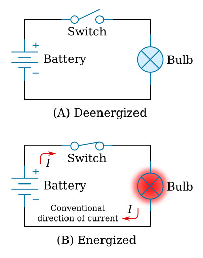
The conventional direction of current is opposite to the direction that electrons actually flow (see the flashlight schematic below). This convention was established in the time when the current was believed to be a flow of positive charge.
There are three basic types of current, distinguished by the ways in which they vary in direction and magnitude.
- Pure direct current (DC) flows in one direction only, and varies only slightly (if at all) in magnitude.
- Pulsating DC is a current whose direction is constant, but whose magnitude varies considerably in a short interval of time.
- Alternating current (AC) varies in both magnitude and direction. That is, the direction of the current periodically reverses.
Voltage Sources
A voltage source is a device which is capable of supplying and maintaining voltage while some type of electrical apparatus is connected to its terminals. The internal action of the source is such that electrons are continuously removed from one terminal, keeping it positive, and simultaneously supplied to the second terminal which maintains a negative charge.
The most common devices for supplying the voltage are batteries and generators. Batteries are widely used as sources of direct-current electrical energy. A generator is a machine that converts mechanical energy into electrical energy (AC or DC) by using the principle of magnetic induction.
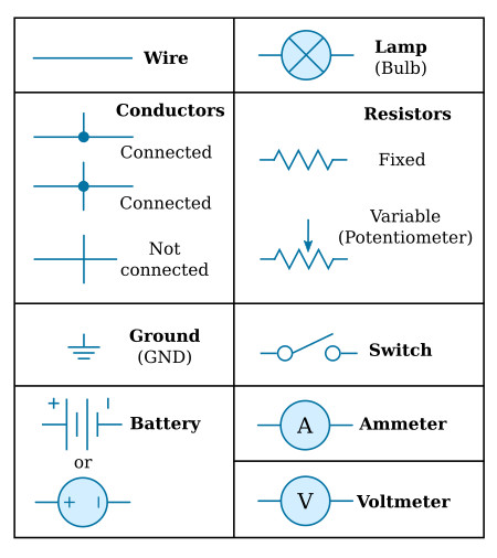
Schematic Diagram
The schematic diagram is a "picture" of the circuit that uses symbols to represent the various circuit components; physically large or complex circuits can be shown on a relatively small diagram. Before studying the basic schematic, look at the figure below. This figure shows the symbols that are commonly used. These, and others like them, are referred to and used throughout the study of electricity and electronics.
The Basic Electric Circuit
The flashlight is an example of a basic electric circuit. It contains a source of electrical energy (the battery), a load (the bulb) which changes the electrical energy into a more useful form of energy (light), and a switch to control the energy delivered to the load.
Before you study a schematic representation of the flashlight, it is necessary to define certain terms. The load is any device through which an electrical current flows and which changes this electrical energy into a more useful form. Some common examples of loads are a lightbulb, which changes electrical energy to light energy; an electric motor, which changes electrical energy into mechanical energy; and the speaker in a radio, which changes electrical energy into sound. The switch, which permits control of the electrical device, interrupts the current delivered to the load.
The schematic in figure below represents a flashlight. View A of the figure shows the flashlight in the off or deenergized state. The switch is open. There is no complete path for current (I) through the circuit, and the bulb (lamp) does not light. In view B, switch is closed. Current flows in the direction of the arrows from the positive terminal of the battery, through the switch, through the lamp, and back to the negative terminal of the battery. With the switch closed the path for current is complete. Current will continue to flow until the switch is moved to the open position or the battery is completely discharged.