


Home > Textbooks > Basic Electronics > DC Circuits > Voltage Dividers >
DC Circuits
Voltage Dividers
Many electrical and electronics equipment use voltages of various levels throughout their circuitry. One circuit may require a 9-volt supply, another a 15-volt supply, and still another a 18-volt supply. These voltage requirements could be supplied by three individual power sources. This method is expensive and requires a considerable amount of room. The most common method of supplying these voltages is to use a single voltage source and a voltage divider.
A typical voltage divider consists of two or more resistors connected in series across a source voltage (Vin). The source voltage must be as high or higher than any voltage developed by the voltage divider. As the source voltage is dropped in successive steps through the series resistors, any desired portion of the source voltage may be "tapped off" to supply individual voltage requirements. The values of the series resistors used in the voltage divider are determined by the voltage and current requirements of the loads.
Consider the circuit of figure below, which represents a simple voltage divider. Physically we know that if Vin is applied to the input, the output VR2 will be less than Vin because some of Vin is used up in forcing current through resistor R1. The amount of voltage used up in R1 is VR1.
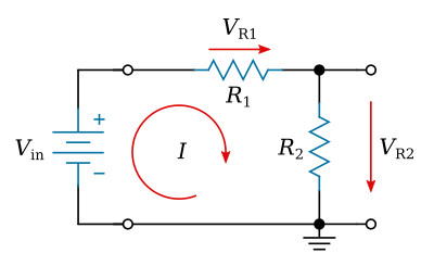
Likewise, the voltage appearing across R2 is VR2, the output voltage in this circuit. Now we should like to find a ready means of determining the voltage across R2, which we are calling VR2. (Vin, R1 and R2 are assumed known.)
By Ohm's law we know that the voltage across a specific resistor is equal to the current through that resistor multiplied by the ohmic value of the resistor. In equation form we would write VR2 = I × R2.
Apparently, to evaluate VR2, we must first determine I. Recalling that I in the simple series circuit shown is

we can then substitute this value of I in the original expression for VR2 — the first equation above — and obtain

The quantity R2/(R1+R2) is then seen to be the ratio between the output and the input voltages.
If we were interested in the voltage across R1, it would be equal to

If a load resistance is placed across any of the resistors, voltage will be supplied to the load resistance and current will be drawn by it. When current is drawn from the divider, the total current flowing in the circuit will increase because the total resistance of the circuit has decreased.
If the total current flowing in the divider circuit is affected by the loads placed on it, then the voltage drops of each divider resistor will also be affected. When a voltage divider is being designed, the maximum current drawn by the loads will determine the value of the resistors that form the voltage divider. Normally, the resistance values chosen for the divider will permit a current equal to ten percent of the total current drawn by the external loads. This current which does not flow through any of the load devices is called bleeder current.
Example:
A simple voltage divider with no load applied is shown in the figure below.
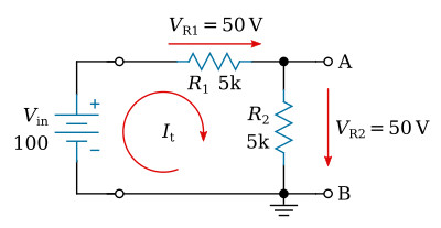
The voltage divider illustrated is composed of two resistors of equal value. Therefore, the voltage drop across each resistance will be the same. The total current flowing in the circuit will be

The potential difference between points (A) and (B) is equal to 50 V. If a resistor is placed between (A) and (B), the voltage drop between these points will be reduced.
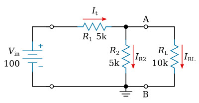
The figure above shows the same divider circuit with a load resistor connected. The total resistance may be computed

It can be seen that the total resistance has decreased. This results in a corresponding increase in current flow. Total current is determined as follows

An analysis of the voltage drops shows the following change in the voltage distribution of the circuit

Notice that while the value of the voltage between points (A) and (B) is reduced the voltage drop across R1 is increased. The amount of current flow through the load can be found in this manner

The variation of voltages and currents found in the previous example are undesirable in a voltage divider. It must be designed to provide voltages that are as stable as possible. A voltage divider consisting of two resistors will be designed using the circuit configuration shown in the figure below. The supply voltage is 200 V. It is desired to furnish a voltage of 50 V to the load drawing 6 mA.
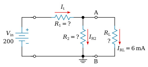
Assume bleeder current to be ten percent of the required load current.
Total load current (IRL) is specified as 6 mA. The bleeder current through R2, therefore should be
![]()
The bleeder current and the current through resistor RL combine and both currents flow through R1. This current value may be computed
![]()
The resistance value of RL must be as follows

Computing for R1 and R2


