


Home > Textbooks > Basic Electronics > DC Circuits > Kirchhoff's Voltage Law >
DC Circuits
Kirchhoff's Voltage Law
In 1847, G. R. Kirchhoff extended the use of Ohm's law by developing a simple concept concerning the voltages contained in a series circuit loop. Kirchhoff's voltage law states:
The algebraic sum of the voltages in any closed path in a circuit is equal to zero.
Kirchhoff's voltage law can be written as an equation, as shown below:
![]()
where V1, V2, etc., are the voltages around any closed circuit loop.
Through the use of Kirchhoff's law, circuit problems can be solved which would be difficult, and often impossible, with knowledge of Ohm's law alone. When Kirchhoff's law is properly applied, an equation can be set up for a closed loop and the unknown circuit values can be calculated.
Polarity of Voltage
To apply Kirchhoff's voltage law, the meaning of voltage polarity must be understood.
In the circuit shown in figure below, the current is shown flowing in a counterclockwise direction. Notice that the end of resistor R1, into which the current flows, is marked positive (+). The end of R1 at which the current leaves is marked negative (-). These polarity markings are used to show that the end of R1 into which the current flows is at a higher positive potential than the end of the resistor at which the current leaves. Point A is more positive than point B.
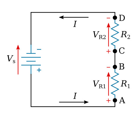
Point C, which is at the same potential as point B, is labeled positive. This is to indicate that point C is more positive than point D. To say a point is positive (or negative) without stating what the polarity is based upon has no meaning. In working with Kirchhoff's law, positive and negative polarities are assigned in the direction of current flow.
The polarity of voltage can also be denoted by an arrow pointing from positive (+) point to negative (-) point (the red arrow in the figure above). In the case of resistors, the voltage arrow has the same direction as the current. This is frequently more practical indication of polarities.
Application of Kirchhoff's Voltage Law
Kirchhoff's voltage law is applied to a circuit in the following manner:
Assume a direction of current through the circuit. (The correct direction is desirable but not necessary.)
Using the assumed direction of current, assign polarities of voltages to all resistors through which the current flows.
Place the correct polarities on any sources included in the circuit.
Starting at any point in the circuit, trace around the circuit (loop) in a
chosen direction (clockwise or counterclockwise), writing down the amount
and polarity of the voltage across each component in succession. The polarity
used is the sign before the assumed current has passed through the
component. Stop when the point at which the trace was started is reached.
When arrows are used for indicating voltage polarities,
the polarity (sign) of voltage can be obtained with the help of the following
rule: If an arrow has the same direction as the trace, the sign of voltage in
the equation is positive (+). In contrast, if an arrow has the opposite
direction, the sign is negative (-).
Place these voltages, with their polarities, into the equation and solve for the desired quantity.
Example:
Three resistors are connected across a 50-volt source (see the figure below).
What is the voltage across the third resistor if the voltage drops across
the first two resistors are 25 volts and 15 volts?
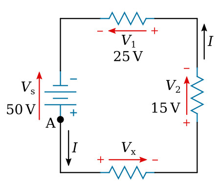
Solution:
First, a direction of current is assumed (as shown). Using this current,
the polarity markings ("+" and "-" signs and/or arrows) are placed at each end
of each resistor and also on the terminals of the source. Starting at point A,
trace around the circuit in the direction of current flow, recording the
voltage and polarity of each component. Starting at point A and
using the components from the circuit:
![]()
Substituting values from the circuit:

The unknown voltage (Vx) is found to be 10 V.
Using the same idea as above, you can solve a problem in which the current is the unknown quantity.
Example:
A circuit having a source voltage of 60 volts contains three resistors
of 5 ohms, 10 ohms, and 15 ohms. Find the circuit current.
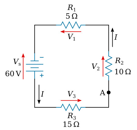
Solution: Draw and label the circuit (figure above). Establish a direction of current flow and assign polarities. Next, starting at any point—point A will be used in this example—write out the loop equation.
Basic equation:
![]()
Since V=I×R, by substitution:
![]()
Combining like terms:
![]()
Computing I:

Since the current obtained in the above calculations is a positive 2 amps, the assumed direction of current was correct. To show what happens if the incorrect direction of current is assumed, the problem will be solved as before, but with the opposite direction of current. The circuit is redrawn showing the new direction of current and new polarities in the figure below. Starting at point A the loop equation is:
Basic equation:
![]()
Since V=I×R, by substitution:
![]()
Combining like terms:
![]()
Computing I:

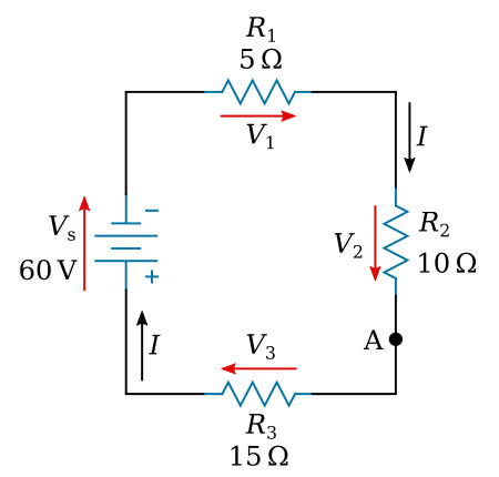
Notice that the amount of current is the same as before. The polarity, however, is negative. The negative polarity simply indicates the wrong direction of current was assumed. Should it be necessary to use this current in further calculations on the circuit using Kirchhoff's law, the negative polarity should be retained in the calculations.


