


Home > Textbooks > Basic Electronics > DC Circuits > Voltage Reference (Ground) >
DC Circuits
Voltage Reference (Ground)
Reference Points
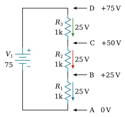
A reference point is an arbitrarily chosen point to which all other points are compared. In a circuit, any point can be chosen as a reference and the electrical potential at all other points can be determined in reference to the initial point. In the example of figure below, point (A) will be considered as the reference. Each series resistor in the illustrated circuit is of equal value; therefore, the applied voltage is equally distributed across each resistor. The potential at point (B) is 25 volts more positive than (A). Points (C) and (D) are 50 volts and 75 volts respectively more positive than point (A).
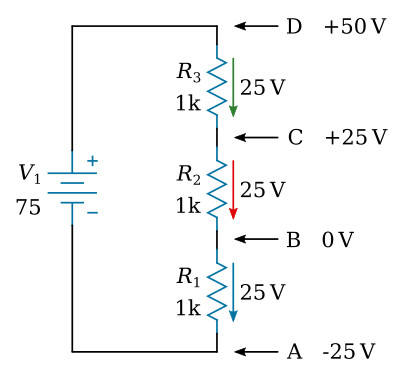
If point (B) is used as the reference as in the figure below, point (D) would be positive 50 volts in respect to the new reference point (B). The former reference point (A) is twenty-five volts negative in respect to point (B).
Ground
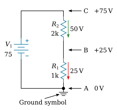
As in the previous circuit illustration, the reference point of a circuit is always considered to be at zero potential. Since the earth (ground) is said to be at a zero potential, the term ground is used to denote a common electrical point of zero potential. In the following figure, point (A) is the zero reference or ground and is symbolized as such. Point (C) is 75 volts positive and point (B) is 25 volts positive in respect to ground.
In most electronic equipments, the metal chassis is the common ground for the many electrical circuits. The value of ground is noted when considering its contribution to economy, simplification of schematics, and ease of measurement. When completing each electrical circuit, common points of a circuit at zero potential are connected directly to the metal chassis thereby eliminating a large amount of connecting wire. The electrons pass through the metal chassis (conductor) to reach other points of the circuit.
Most voltage measurements used to proper circuit operation in electronic equipment are taken in respect to ground. One lead is attached to ground and the other lead is moved to various test points.


