


Home > Textbooks > Basic Electronics > DC Circuits > Series DC Circuits >
DC Circuits
Series DC Circuits
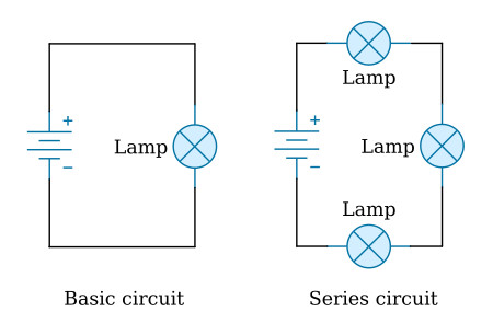
A series circuit is defined as a circuit that contains only one path for current flow. To compare the basic circuit and a more complex series circuit, the figure below shows two circuits. The basic circuit has only one lamp and the series circuit has three lamps connected in series.
Resistance in a Series Circuit
Referring to the figure above, the current in a series circuit must flow through each lamp to complete the electrical path in the circuit. Each additional lamp offers added resistance. In a series circuit, the total circuit resistance Rt is equal to the sum of the individual resistances.
As an equation:
![]()
Note: The subscript n denotes any number of additional resistances that might be in the equation.
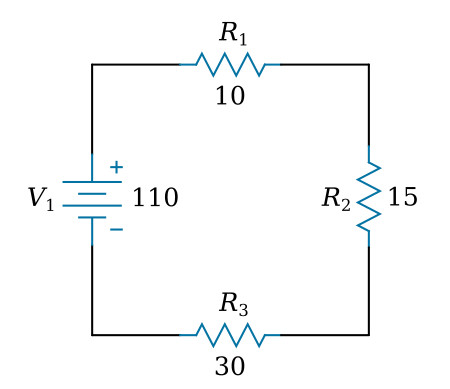
Example: In the figure below a series circuit consisting of three resistors: one of 10 Ω, one of 15 Ω, and one of 30 Ω, is shown. A voltage source provides 110 V. What is the total resistance?
Given:
R1 = 10 Ω, R2 = 15 Ω, R3 = 30 Ω
Solution:
![]()
In some circuit applications, the total resistance is known and the value of one of the circuit resistors has to be determined. The equation Rt = R1 + R2 + R3 can be transposed to solve for the value of the unknown resistance.
Example:
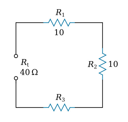
In the figure below the total resistance of a circuit
containing three resistors is 40 Ω. Two of the circuit resistors are
10 Ω each. Calculate the value of the third resistor (R3).
Given:
Rt = 40 Ω, R1 = 10 Ω, R2 = 10 Ω,
R3 = ?
Solution:
![]()
Subtracting (R1 + R2) from both sides of the equation

Current in a Series Circuit
Since there is only one path for current in a series circuit, the same current must flow through each component of the circuit. To determine the current in a series circuit, only the current through one of the components need be known.
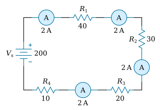
The fact that the same current flows through each component of a series circuit can be verified by inserting meters into the circuit at various points, as shown in the figure below. If this were done, each meter would be found to indicate the same value of current.
Voltage in a Series Circuit
The voltage dropped across the resistor in a circuit consisting of a single resistor and a voltage source is the total voltage across the circuit and is equal to the applied voltage. The total voltage across a series circuit that consists of more than one resistor is also equal to the applied voltage, but consists of the sum of the individual resistor voltage drops. In any series circuit, the sum of the resistor voltage drops must equal the source voltage. This statement can be proven by an examination of the circuit shown in the figure below.
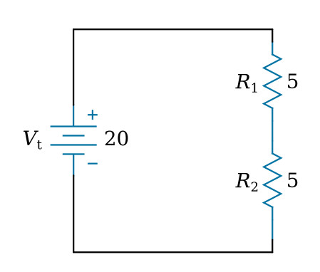
In this circuit a source potential (Vt) of 20 V is dropped across a series circuit consisting of two 5-ohm resistors. The total resistance of the circuit (Rt) is equal to the sum of the two individual resistances, or 10 Ω. Using Ohm’s law the circuit current may be calculated as follows:
Given: Vt = 20 V, Rt = 10 Ω
Solution:

Since the value of the resistors is known to be 5 Ω each, and the current through the resistors is known to be 2 A, the voltage drops across the resistors can be calculated. The voltage (V1) across R1 is therefore:
Given: I1 = 2 A, R1 = 5 Ω
Solution:
![]()
By inspecting the circuit, you can see that R2 is the same ohmic value as R1 and carries the same current. The voltage drop across R2 is therefore also equal to 10 V. Adding these two 10-volts drops together gives a total drop of 20 V, exactly equal to the applied voltage. For a series circuit then:
![]()
Example: A series circuit consists of three resistors having values of 20 Ω, 30 Ω, and 50 Ω, respectively. Find the applied voltage if the current through the 30 Ω resistor is 2 A.
To solve the problem, a circuit diagram is first drawn and labeled (figure below).
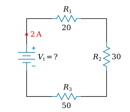
Given: R1 = 20 Ω, R2 = 30 Ω, R3 = 50 Ω, I = 2 A
Solution: Since the circuit involved is a series circuit, the same 2 A of current flows through each resistor. Using Ohm's law, the voltage drops across each of the three resistors can be calculated and are:

Once the individual drops are known they can be added to find the total or applied voltage:

Note: When you use Ohm’s law, the quantities for the equation must be taken from the same part of the circuit. In the above example the voltage across R2 was computed using the current through R2 and the resistance of R2.
The value of the voltage dropped by a resistor is determined by the applied voltage and is in proportion to the circuit resistances. The voltage drops that occur in a series circuit are in direct proportion to the resistances. This is the result of having the same current flow through each resistor—the larger the ohmic value of the resistor, the larger the voltage drop across it.


