


Home > Textbooks > Basic Electronics > DC Circuits > Parallel DC Circuits >
DC Circuits
Parallel DC Circuits
A parallel circuit is defined as one having more than one current path connected to a common voltage source. Parallel circuits, therefore, must contain two or more resistances which are not connected in series. An example of a basic parallel circuit is shown in the figure below.
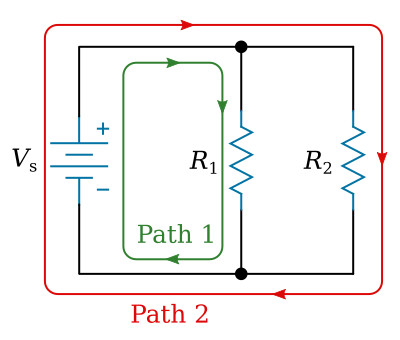
Start at the voltage source (Vs) and trace clockwise around the circuit. Two complete and separate paths can be identified in which current can flow. One path is traced from the source, through resistance R1, and back to the source. The other path is from the source, through resistance R2, and back to the source.
Voltage in a Parallel Circuit
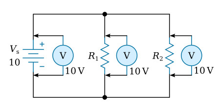
You have seen that the source voltage in a series circuit divides proportionately across each resistor in the circuit. In a parallel circuit, the same voltage is present in each branch. (A branch is a section of a circuit that has a complete path for current.) In the figure above this voltage is equal to the applied voltage (Vs). This can be expressed in equation form as:
![]()
Voltage measurements taken across the resistors of a parallel circuit, as illustrated by the figure below verify this equation. Each meter indicates the same amount of voltage. Notice that the voltage across each resistor is the same as the applied voltage.
Example: Assume that the current through a resistor of a parallel circuit is known to be 4.5 mA and the value of the resistor is 30 kΩ. Determine the source voltage. The circuit is shown in the figure below.
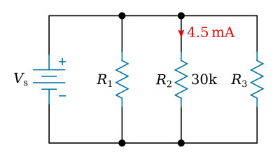
Given: R2 = 30 kΩ, IR2 = 4.5 mA
Find: VR2 = ?, Vs = ?
Solution: Select proper equation:
![]()
Substitute known values:
![]()
Since the source voltage is equal to the voltage of a branch:
![]()
Current in a Parallel Circuit
Ohm’s law states that the current in a circuit is inversely proportional to the circuit resistance. This fact is true in both series and parallel circuits.
There is a single path for current in a series circuit. The amount of current is determined by the total resistance of the circuit and the applied voltage. In a parallel circuit the source current divides among the available paths.
The behavior of current in parallel circuits will be shown by a series of illustrations using example circuits with different values of resistance for a given value of applied voltage.
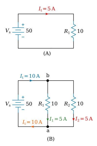
Part (A) of the figure above shows a basic series circuit. Here, the total current must pass through the single resistor. The amount of current can be determined.
Given:
Vs = 50 V, R1 = 10 Ω
Solution:

Part (B) of the figure above shows the same resistor (R1) with a second resistor (R2) of equal value connected in parallel across the voltage source. When Ohm’s law is applied, the current flow through each resistor is found to be the same as the current through the single resistor in part (A).
Given:
Vs = 50 V, R1 = 10 Ω, R2 = 10 Ω
Solution:

It is apparent that if there is 5 amperes of current through each of the two resistors, there must be a total current of 10 amperes drawn from the source.
The total current of 10 A, as illustrated in the figure above (part B), leaves the positive terminal of the battery and flows to point b. Since point b is a connecting point for the two resistors, it is called a junction. At junction b, the total current divides into two currents of 5 amperes each. These two currents flow through their respective resistors and rejoin at junction a. The total current then flows from junction a back to the negative terminal of the source. The source supplies a total current of 10 A and each of the two equal resistors carries one-half the total current.
Each individual current path in the circuit of the figure above (part B) is referred to as a branch. Each branch carries a current that is a portion of the total current. Two or more branches form a network.
From the previous explanation, the characteristics of current in a parallel circuit can be expressed in terms of the following general equation:
![]()
Compare part (A) of the figure below with part (B) of the circuit in the figure above. Notice that doubling the value of the second branch resistor (R2) has no effect on the current in the first branch (I1), but does reduce the second branch current (I2) to one-half its original value. The total circuit current drops to a value equal to the sum of the branch currents. These facts are verified by the following equations.
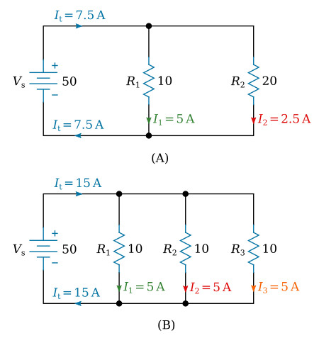
Given:
Vs = 50 V, R1 = 10 Ω, R2 = 20 Ω
Solution:

The amount of current flow in the branch circuits and the total current in the circuit shown in the figure above (part B) are determined by the following computations.
Given:
Vs = 50 V, R1 = 10 Ω, R2 = 10 Ω, R3 = 10 Ω
Solution:

Notice that the sum of the ohmic values in each circuit shown in the figure above is equal (30 Ω), and that the applied voltage is the same (50 V). However, the total current in part (B) (15 A) is twice the amount in part (A) (7.5 A). It is apparent, therefore, that the manner in which resistors are connected in a circuit, as well as their actual ohmic values, affect the total current.
The division of current in a parallel network follows a definite pattern. This pattern is described by Kirchhoff's current law.


