


Home > Textbooks > Basic Electronics > Tests and Measurements > Capacitance Measurements >
Tests and Measurements
Capacitance Measurements
Capacitance measurements are usually accomplished by either a bridge-type or a reactance-type capacitance meter. In addition to its capacitance, the capacitor under test always exhibits some losses. Capacitors incur losses as a result of such factors as resistance in the conductors (plates) or leads, current leakage, and dielectric absorption, all of which affect the power factor of the capacitor. Theoretically, the power factor of an ideal capacitor should be zero; however, the losses listed above cause the power factors of practical capacitors to range from near 0 to a possible 100%. The losses may have the characteristics of either a shunt or series resistance, or it may be a combination of both. These resistances should be considered when measuring capacitance.
Capacitors can retain a charge long after the voltage has been removed. The electrical charge retained by capacitors in de-energized electronic circuits is, in many cases, sufficient to cause a lethal shock. Be sure you and those working with you consider this hazard before performing any type of maintenance on any electrical or electronic circuit and before making connections to a seemingly dead circuit. Use extreme caution prior to working on de-energized circuits that employ large capacitors.
Bridge-Type Measurements
You can measure capacitance, inductance, and resistance for precise accuracy by using AC bridges. These bridges are composed of capacitors, inductors, and resistors in a wide variety of combinations. The AC bridges operate on the principle of the Wheatstone bridge; that is, an unknown resistance is balanced against known resistances and, after the bridge has been balanced, the unknown resistance is calculated in terms of the known resistance.
Regardless of its true nature, the capacitor loss can be represented as a simple series resistance. Therefore, capacitance can be measured in terms of a two-element equivalent circuit consisting of a capacitor in series with a resistor, which is shown in the figure below as Rx.
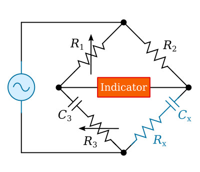
Figure above is a schematic of a capacitance bridge. As you can see, a capacitance bridge is very similar in construction to a resistance bridge with the exception of the standard capacitor (C3) and the unknown capacitor (Cx).
The general condition for balance of the AC bridge is (see here)
![]()
We may write the impedances for our case

After substituting these impedance into the general condition (Z1 Z4 = Z2 Z3)

Equality of two complex numbers requires that the real parts be equal on the two sides of the equation, likewise the j terms. Therefore

Thus, both the unknown resistance and capacitance, Rx and Cx, can be estimated in terms of known resistance R1, R2, R3, and known capacitance C3. The balance conditions require that two quantities be variable in this bridge as, for example, R1 (or R2) and R3.
Reactance-Type Measurements
The reactance type of capacitance measuring equipment makes use of the following principle: If an AC voltage at a fixed frequency is applied across a capacitor and resistor in series, the voltage drop produced across the reactance of the capacitor by the resulting current flow is inversely proportional to the capacitance. The voltage drop is used to actuate a meter that is calibrated in capacitance values. The accuracy of the reactance-type measurement is less for capacitors that have a high power factor. In capacitors with high power factors, the losses incurred effectively place a certain amount of resistance in series with the capacitive reactance. The effect of this resistance, when the capacitor is measured, is to cause a greater voltage drop across the capacitor. This drop is not because of the reactance above, but is the result of the impedance, which of course is made up of both the reactance and the resistance. Therefore, the capacitance indicated by the analyzer will be lower than the actual value. The more advanced instruments also measure the phase angle between the voltage and current, allowing to calculate and display the equivalent capacitance and resistance of the capacitor.

