


Home > Textbooks > Basic Electronics > Tests and Measurements > Voltage Measurements >
Tests and Measurements
Voltage Measurements
Voltages are usually measured by placing the measuring device in parallel with the component or circuit (load) to be measured. The measuring device should have an infinite input impedance (resistance) so that it will absorb no energy from the circuit under test and, therefore, measure the true voltage. The accuracy of the voltage measurement depends on the total impedance of the measuring device compared to the load being measured. When the input impedance of the measuring device is 10 times greater than the load being measured, the error usually can be tolerated. If this error cannot be tolerated, a higher input impedance measuring device should be used.
Multimeter Method
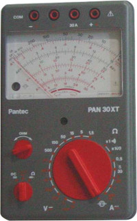
A common piece of test equipment is multimeter. The multimeter contains circuitry that allows it to be used as a voltmeter, an ammeter, or an ohmmeter. It is usually capable of measuring both AC and DC voltages of up to several hundred volts. Most multimeters have a high input impedance and are not likely to disturb the circuit being tested.
The obvious disadvantage of the analog multimeter is the inherent low accuracy associated with meter movements (moving pointers), which are used in the multimeter. When performing measurements with any analog multimeter, you should be aware of inaccuracies introduced as a result of parallax. Parallax is defined as the apparent displacement of the position of an object because of the difference between two points of view. In the case of meters, this means the position of a meter's pointer will appear to be at different positions on the scale depending on the angle from which the meter is viewed.
The digital multimeter in many cases provides an accuracy of about ±0.1%. They display the reading numerically. These direct-reading displays eliminate the problem of parallax, reduce error, and increase measurement speed. Data from these meters in digital format can also be processed by computers, printers, and recording equipment. Digital multimeters are typically compact and lightweight; many come with rechargeable batteries, making them ideal for portable field use.
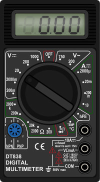
The upper frequency limitations of digital multimeters typically vary from 1 kHz to over 1 MHz, depending on the model. Their upper frequency limitations can, however, be significantly extended by using optional RF probes. When you perform AC voltage measurements with a digital multimeter, remember that they are RMS indicating devices.
Oscilloscope Method
Voltage measurements can be made with an oscilloscope. Oscilloscopes have a high input impedance and normally will not load down the circuit under test. However, oscilloscopes are primarily designed for waveform observation and are typically less accurate than other pieces of test equipment used to measure DC or AC voltages.
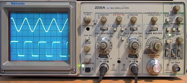
Measuring a DC voltage with an oscilloscope is convenient only under certain circumstances; for example, when other measurements are being made on the same equipment with the oscilloscope or when a multimeter is not available. A distinct advantage of the oscilloscope is its ability to monitor the level of AC ripple voltage riding the DC voltage. This feature makes the oscilloscope an indispensable aid in troubleshooting DC power supplies with excessive ripple caused by component failure.
A major advantage of using an oscilloscope for AC voltage measurements is that the waveform can be observed; consequently, errors in measuring complex peak voltages are minimized.
If a voltage to be measured is large and cannot be attenuated to a usable value by attenuation circuits within the oscilloscope, an external resistive or capacitive voltage divider can be used. Such voltage dividers are often furnished with oscilloscope test sets and are called high voltage probes. When the voltage of pulses or other complex waveforms is being measured, the high voltage probe selected must be so designed as not to distort the measured signal. Most probes have adjustable (compensating) capacitors that are used to adjust the symmetry of the displayed waveform. You adjust the probe by monitoring either the calibrator output of the oscilloscope or a known good signal and adjusting the probe for a symmetrical display.
When using the oscilloscope for AC voltage measurements, ensure the upper frequency range of the oscilloscope is not exceeded; otherwise, inaccurate values will be displayed. Most commonly used oscilloscopes have a frequency response from DC up to about 50 MHz.


