


Home > Textbooks > Solid-State Devices > Bipolar Transistors > Transistor Testing >
BIPOLAR TRANSISTORS
Transistor Testing
There are several different ways of testing transistors. They can be tested while in the circuit, by the substitution method mentioned, or with a transistor tester or ohmmeter.
Transistor testers are nothing more than the solid-state equivalent of electron-tube testers (although they do not operate on the same principle). With most transistor testers, it is possible to test the transistor in or out of the circuit.
There are four basic tests required for transistors in practical troubleshooting: gain, leakage, breakdown, and switching time. For maintenance and repair, however, a check of two or three parameters is usually sufficient to determine whether a transistor needs to be replaced.
Since it is impractical to cover all the different types of transistor testers and since each tester comes with its own operator's manual, we will move on to something you will use more frequently for testing transistors – the ohmmeter.
Testing Transistors with an Ohmmeter
Two tests that can be done with an ohmmeter are gain, and junction resistance. Tests of a transistor's junction resistance will reveal leakage, shorts, and opens.
TRANSISTOR GAIN TEST.–A basic transistor gain test can be made using an ohmmeter and a simple test circuit. The test circuit can be made with just a couple of resistors and a switch, as shown in figure below. The principle behind the test lies in the fact that little or no current will flow in a transistor between emitter and collector until the emitter-base junction is forward biased. The only precaution you should observe is with the ohmmeter. Any internal battery may be used in the meter provided that it does not exceed the maximum collector-emitter breakdown voltage.

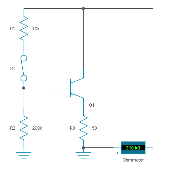
With the switch in figure below in the open position as shown, no voltage is applied to the PNP transistor's base, and the emitter-base junction is not forward biased. Therefore, the ohmmeter should read a high resistance, as indicated on the meter. When the switch is closed, the emitter-base circuit is forward biased by the voltage across R1 and R2. Current now flows in the emitter-collector circuit, which causes a lower resistance reading on the ohmmeter. A 10-to-1 resistance ratio in this test between meter readings indicates a normal gain for an audio-frequency transistor.
To test an NPN transistor using this circuit, simply reverse the ohmmeter leads and carry out the procedure described earlier.
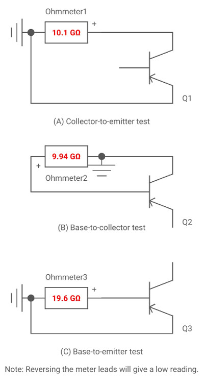
TRANSISTOR JUNCTION RESISTANCE TEST.–An ohmmeter can be used to test a transistor for leakage (an undesirable flow of current) by measuring the base-emitter, base-collector, and collector-emitter forward and reverse resistances.
For simplicity, consider the transistor under test in each view of figure below as two diodes connected back to back. Therefore, each diode will have a low-forward resistance and a high-reverse resistance. By measuring these resistances with an ohmmeter as shown in the figure, you can determine if the transistor is leaking current through its junctions. When making these measurements, avoid using the R 1 scale on the meter or a meter with a high internal battery voltage. Either of these conditions can damage a low-power transistor.
Now consider the possible transistor problems that could exist if the indicated readings in figure above are not obtained. A list of these problems is provided in table below.
| RESISTANCE READINGS | PROBLEMS | |
| FORWARD | REVERSE | The transistor is: |
| LOW (NOT SHORTED) | LOW (NOT SHORTED) | LEAKING |
| LOW (SHORTED) | LOW (SHORTED) | SHORTED |
| HIGH | HIGH | OPEN* |
| *Except collector-to-emitter test. | ||
By now, you should recognize that the transistor used in figure above is a PNP transistor. If you wish to test an NPN transistor for leakage, the procedure is identical to that used for testing the PNP except the readings obtained are reversed.
When testing transistors (PNP or NPN), you should remember that the actual resistance values depend on the ohmmeter scale and the battery voltage. Typical forward and reverse resistances are insignificant. The best indicator for showing whether a transistor is good or bad is the ratio of forward-to-reverse resistance. If the transistor you are testing shows a ratio of at least 30 to 1, it is probably good. Many transistors show ratios of 100 to 1 or greater.

