Home > Textbooks > Basic Electronics > Audio Amplifiers > Equalization Networks >
Audio Amplifiers
Equalization Networks
It is often desirable to shape the frequency response of the amplifier to a prescribed characteristic. This may be done by a method similar to that used in the design of the gain (volume) control circuits discussed previously, except that the gain control resistance must be replaced by a combination of frequency-dependent elements. An example will illustrate the design procedure.
Example.
It is required to compensate the two-stage amplifier for the RIAA playback
characteristic for microgroove records. The preamplifier is to operate from
a variable-reluctance cartridge having the following specification:
peak output at 1 kHz = 50 mV; terminating resistance for a
high-frequency roll-off at 2120 Hz = 6200 ohms.
The figure below shows the RIAA playback characteristic.
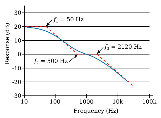
Since the high-frequency roll-off is obtained by terminating the cartridge in a 6200 ohms load, it is only necessary to design a compensating network for the response characteristic of the figure below. We choose to place the compensation networks in the first stage in order to obtain a minimum operating dynamic range for the transistors.
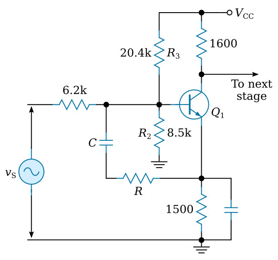
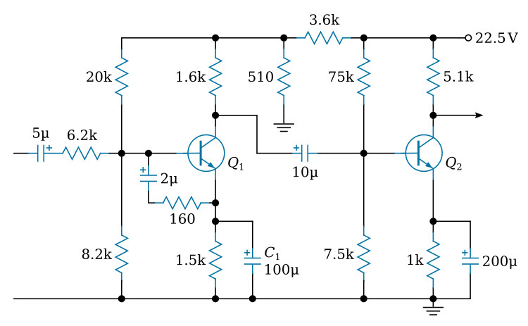
The circuit will take the form of the figure above. The equivalent circuit is shown in the figure below (view A), with R2, R3, and the 6200 ohms resistance combined in parallel in a common term Rg.
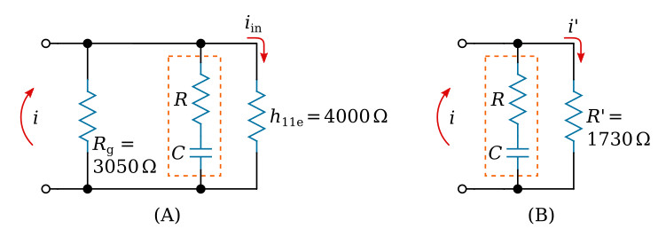
This may be further redrawn in the form of the figure above (view B) where R' is the parallel combination of Rg and h11e.
Then

Since

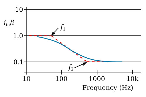
the current entering the transistor (iin) has the same frequency characteristic as i'.
At high frequencies, the output is down to 0.1 of its initial value. Therefore

The frequency f2 occurs when R is equal to the reactance of the capacitor; whence C = 1.7 μF.
A study of the RIAA playback characteristic shows that the location of f2 determines the amount of bass boost over the entire low-frequency range, whereas the location of f1 determines only the gain at very low frequencies. Thus, while f1 may be varied considerably without much apparent effect, it is important that the location of f2 be maintained critically. This will be accomplished if the product of R and C is maintained constant. With this restriction in mind, minor changes in C are permissible. In general, it is preferable to increase C since this will lower f1 slightly. In the final design, this may result in a reduction in the size of the emitter bypass capacitance. The final version is shown in the figure below.