


Home > Textbooks > Basic Electronics > Audio Amplifiers > Power Stages >
Audio Amplifiers
Power Stages
The power stage (high-level stage) has been defined as one in which the active element (e.g. transistor) operates at power levels measured in hundreds of milliwatts or in watts. Although the principles discussed in the preceding section about low-level stages (preamplifiers) are still applicable, the design of a high-level stage will present many special problems of its own. Here the excursions of the bias voltages and currents may approach the absolute limits of operation of the transistor. Therefore, the selection of the operating point and load become of paramount importance.
In most audio amplifiers, high-level operation will occur only in the output stage, or in those stages immediately preceding it. Thus the discussion of the high-level stage is essentially that of the output stage.
The choice of the transistor configuration and mode of operation of the output stage will be influenced by many factors, some of which are: (a) power output, (b) DC power requirement, (c) power gain, (d) nonlinear distortion, (e) frequency response. The modes of operation that may be utilized are class A and class AB.
Class A Operation
In class-A operation, the transistor conducts over the entire cycle, and the output waveform is a reasonable copy of the input signal. It is therefore possible to utilize a single transistor for a class-A stage.
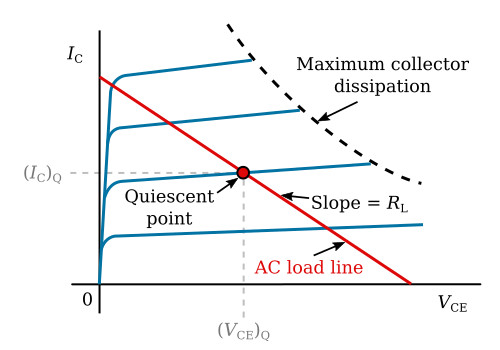
The operation of such a stage is readily visualized with the aid of the output characteristic for the configuration of interest. The figure below shows the output characteristics of a transistor in the common-emitter configuration. On this figure is shown also the curve for maximum permissible collector dissipation for a specified cooling technique and a specified ambient temperature. The product of the voltage and current at every point of this curve is equal to the maximum dissipation. The operating point must lie to the left of the maximum dissipation curve.
The first problem is the selection of the power supply voltage VCC. Consider a transformer-coupled stage. The output-transformer action will cause the peak AC voltage across load (the output-transformer primary) to be as high as twice the supply
![]()
The maximum collector-voltage rating (VCEmax) of transistor should be higher than Vpeak by a safety factor, say 30 percent
![]()
VCC will be

The next step in the location of the operating point (or the Q-point). Let the operating point be at (VCE)Q, (IC)Q. The output-transformer primary resistance may be neglected, and so the supply voltage will also be (VCE)Q.
(IC)Q can be determined from the AC power output (see the Amplifiers section)

In class-A operation, maximum collector dissipation (Pdis) occurs for the zero-signal condition. For this condition
![]()
DC battery power PDC is
![]()
This is also the standby dissipation power of the transistor (Pdis).
The value of the AC load resistance RL is obtained from the AC load line (see the figure above) and is

Design of a Class-A Output Stage
Example:
Design a common-emitter stage with the following specifications:
Power output: Pload = 3 W
Transformer efficiency: η = 0.75
Supply voltage: VCC = 28 V
For an output of 3 W, the stage must supply power PAC = 3/0.75 = 4 W to the primary winding of the transformer. Collector dissipation is then
![]()
Therefore

Load resistance is

We select a transistor that is capable of 8 W dissipation for the given ambient conditions, and has a permissible collector-emitter voltage in excess of 73 V (VCEmax = 2.6×VCC).
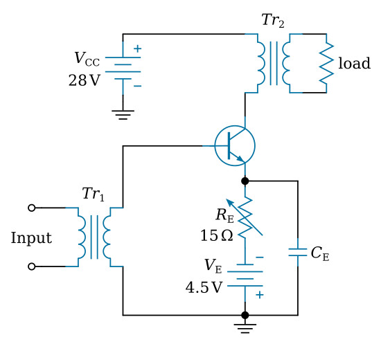
A possible circuit configuration is shown in the figure below. For stabilization, we may use a 4.5-volt emitter supply and a resistance of RE=(VE-VBE)/IE =(4.5-0.7)/0.286=13.3 Ω. The value of this resistance may have to be adjusted to give the required operating point.
If the load is to be a 4-ohm speaker, a transformer will be needed to couple the 4-ohm voice coil to the transistor. The impedance ratio (RL/Rspeaker) must be 97.9:4≅24:1. So a transformer having a turns ratio of approximately 5:1 (square root of the impedance ratio equals the turns ratio) will do the job.


