


Home > Textbooks > Basic Electronics > Amplifiers > Class A Amplifiers >
Amplifiers
Class A Amplifiers
Class A amplifiers are usually used in equipments in which large power outputs are not required. When a class A transistor amplifier is used in power stages, transistors may be operated in the common-emitter, the common-base, and the common-collector configurations. In addition, any configuration may have a single-ended (one transistor) or a push-pull arrangement. When compared with push-pull stages, single-ended stages produce more distortion and have lower efficiency.
In the analysis and design of a power amplifier, the necessary considerations are (a) power efficiency, (b) maximum power dissipation capability of the transistor, (c) distortion, (d) frequency response.
Transistors in power amplifiers are merely control devices that permit the conversion of the DC power applied to the circuit to useful AC power in the load impedance. Because of the resistance of the transistor and the current through it, the device dissipates power; therefore, it can never be 100 percent efficient.
Power Efficiency
The power efficiency is a measure of how well a power amplifier converts DC power from the supply (PDC) to useful AC power delivered to the load (PAC). The formula for percentage of power efficiency is

The formula as stated is basic and is used to express several different values of efficiency for any given amplifier. In the transistor circuit, the collector efficiency is probably the value most often used. The collector efficiency is determined by using the collector supply voltage (VCC) times the collector current (IC)

When the single stage power amplifiers are terminated in resistive load impedances, a resistor in the collector circuit of a transistor would dissipate power, even in a static state. This represents a reduction in efficiency; and in order to avoid this, transformer coupling is used. By using a transformer, the only resistance in the collector circuit is the very small DC resistance of the primary winding. Thus, the DC power dissipation is greatly reduced, and the efficiency is increased.
Transformer-Coupled Amplifier
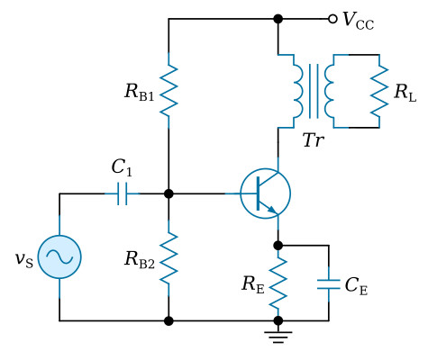
Consider a transformer-coupled stage (see the figure above). The AC power output of the circuit will be evaluated by the product of the AC collector (output) voltage VC and the AC current flowing through the collector of the transistor (IC). The root mean square (rms) value of the sine wave collector voltage is defined as

Similarly, the rms value of the collector current is

Consequently, the AC power output is defined by the product of VC(rms) and IC(rms). Thus

The supply power must be the product of the supply voltage and current. Mathematically, the equation is
![]()
The efficiency in converting the DC power supplied to the collector circuit into AC power is

The optimum efficiency of a class A power amplifier can be determined for an ideal transistor. An ideal transistor is one whose characteristics are perfectly linear. Consequently, the maximum voltage and current swings for an ideal transistor are

The optimum efficiency is then

In the practical operation of the amplifier, the optimum efficiency is never achieved. This efficiency may be used, however, for comparison purposes and for preliminary calculations in the design of a class A power stage.


