


Home > Textbooks > Basic Electronics > Amplifiers > Impedances of Amplifiers >
Amplifiers
Impedances of Amplifiers
The most efficient device is the one that does the job with the least loss of power. One of the largest losses of power is caused by impedance differences between the output of one circuit and the input of the next circuit. Perhaps the best way to think of an impedance difference (mismatch) between circuits is to think of different-sized water pipes. If you try to connect a one-inch water pipe to a two-inch water pipe without an adapter you will lose water. You must use an adapter. A impedance-matching device is like that adapter. It allows the connection of two devices with different impedances without the loss of power.
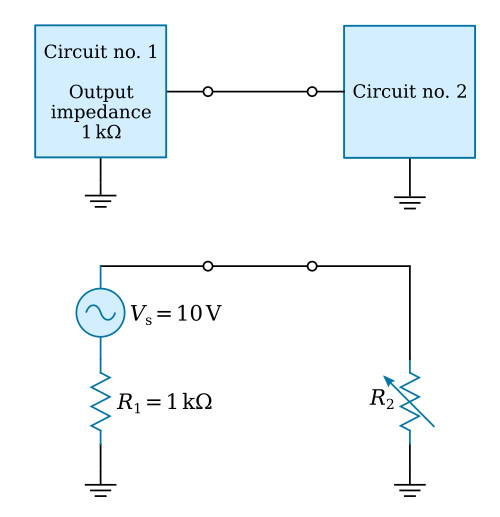
The figure below shows two circuits connected together. Circuit number 1 can be considered as an AC source (VS) whose output impedance is represented by a resistor (R1). It can be considered as an AC source because the output signal is an AC voltage and comes from circuit number 1 through the output impedance. The input impedance of circuit number 2 is represented by a resistor in series with the source. The resistance is shown as variable to show what will happen as the input impedance of circuit number 2 is changed.
| R2 [Ω] | I [mA] | VR2 [V] | PR1 [mW] | PR2 [mW] |
|---|---|---|---|---|
| 100 | 9 | 0.9 | 82.6 | 8.3 |
| 200 | 8.3 | 1.67 | 69.4 | 13.9 |
| 500 | 6.7 | 3.33 | 44.4 | 22.2 |
| 1000 | 5 | 5 | 25 | 25 |
| 2000 | 3.3 | 6.67 | 11.1 | 22.2 |
| 5000 | 1.7 | 8.33 | 2.7 | 13.9 |
| 10000 | 9 | 9.09 | 9 | 8.3 |
The chart below the circuit shows the effect of a change in the input impedance of circuit number 2 (R2) on current (I), signal voltage developed at the input of circuit number 2 (VR2), the power at the output of circuit number 1 (PR1), and the power at the input to circuit number 2 (PR2).
Two important facts are brought out in this chart. First, the power at the input to circuit number 2 is greatest when the impedances are equal (matched). The power is also equal at the output of circuit number 1 and the input of circuit number 2 when the impedance is matched. The second fact is that the largest voltage signal is developed at the input to circuit number 2 when its input impedance is much larger than the output impedance of circuit number 1. However, the power at the input of circuit number 2 is very low under these conditions. So you must decide what conditions you want in coupling two circuits together and select the components appropriately.
Two important points to remember about impedance matching are as follows. (1) Maximum power transfer requires matched impedance. (2) To get maximum voltage at the input of a circuit requires an intentional impedance mismatch with the circuit that is providing the input signal.
Impedance Characteristics of Amplifier Configurations
Now that you have seen the importance of impedance matching the stages in an electronic device, you may wonder what impedance characteristics an amplifier has. The input and output impedances of a transistor amplifier depend upon the configuration of the transistor. In Bipolar Junction Transistors chapter, you were introduced to the three transistor configurations; the common emitter, the common base, and the common collector. Examples of these configurations and their impedance characteristics are shown in the figure below.
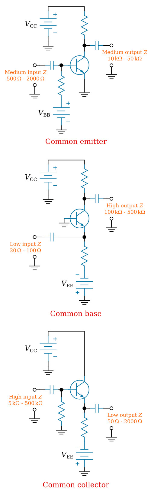
NOTE: Only approximate impedance values are shown. This is because the exact impedance values will vary from circuit to circuit. The impedance of any particular circuit depends upon the device (transistor) and the other circuit components. The value of impedance can be computed by dividing the signal voltage by the signal current. Therefore:

The common-emitter configuration provides a medium input impedance and a medium output impedance. The common-base configuration provides a low input impedance and a high output impedance. The common-collector configuration provides a high input impedance and a low output impedance. The common-collector configuration is often used to provide impedance matching between a high output impedance and a low input impedance.


