


Home > Textbooks > Basic Electronics > Amplifiers > Amplifier Feedback >
Amplifiers
Amplifier Feedback
Perhaps you have been around a public address system when a squeal or high-pitched noise has come from the speaker. Someone will turn down the volume and the noise will stop. That noise is an indication that the amplifier (at least one stage of amplification) has begun oscillating. The oscillation is caused by a small part of the signal from the amplifier output being sent back to the input of the amplifier. This signal is amplified and again sent back to the input where it is amplified again. This process continues and the result is a loud noise out of the speaker. The process of sending part of the output signal of an amplifier back to the input of the amplifier is called feedback.
There are two types of feedback in amplifiers. They are positive feedback, also called regenerative feedback, and negative feedback, also called degenerative feedback. The difference between these two types is whether the feedback signal is in phase or out of phase with the input signal.
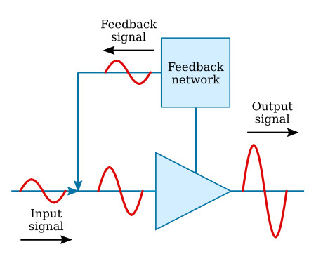
Positive feedback occurs when the feedback signal is in phase with the input signal. The figure below shows a block diagram of an amplifier with positive feedback. Notice that the feedback signal is in phase with the input signal. This means that the feedback signal will add to or "regenerate" the input signal. The result is a larger amplitude output signal than would occur without the feedback. This type of feedback is what causes the public address system to squeal as described above.
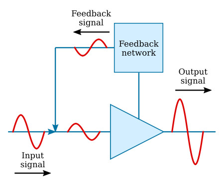
The figure below is a block diagram of an amplifier with negative feedback. In this case, the feedback signal is out of phase with the input signal. This means that the feedback signal will subtract from or "degenerate" the input signal. This results in a lower amplitude output signal than would occur without the feedback.
Sometimes feedback that is not desired occurs in an amplifier. This happens at high frequencies and limits the high-frequency response of an amplifier. Unwanted feedback also occurs as the result of some circuit components used in the biasing or coupling network. The usual solution to unwanted feedback is a feedback network of the opposite type. For example, a positive feedback network would counteract unwanted, negative feedback.
Feedback is also used to get the ideal input signal. Normally, the maximum output signal is desired from an amplifier. The amount of the output signal from an amplifier is dependent on the amount of the input signal. However, if the input signal is too large, the amplifying device will be saturated and/or cut off during part of the input signal. This causes the output signal to be distorted and reduces the fidelity of the amplifier. Amplifiers must provide the proper balance of gain and fidelity.
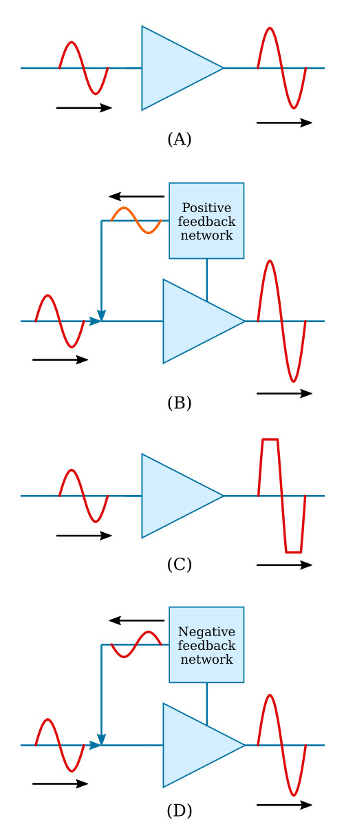
The figure below shows the way in which feedback can be used to provide the maximum output signal without a loss in fidelity. In view A, an amplifier has good fidelity, but less gain than it could have. By adding some positive feedback, as in view B, the gain of the stage is increased. In view C, an amplifier has so much gain and such a large input signal that the output signal is distorted. This distortion is caused by the amplifying device becoming saturated and cutoff. By adding a negative feedback system, as in view D, the gain of the stage is decreased and the fidelity of the output signal improved.
Positive and negative feedback are accomplished in many ways, depending on the reasons requiring the feedback. A few of the effects and methods of accomplishing feedback are presented next.
Positive Feedback
As you have seen, positive feedback is accomplished by adding part of the output signal in phase with the input signal. In a common-base transistor amplifier, it is fairly simple to provide positive feedback. Since the input and output signals are in phase, you need only couple part of the output signal back to the input. This is shown in the figure below.
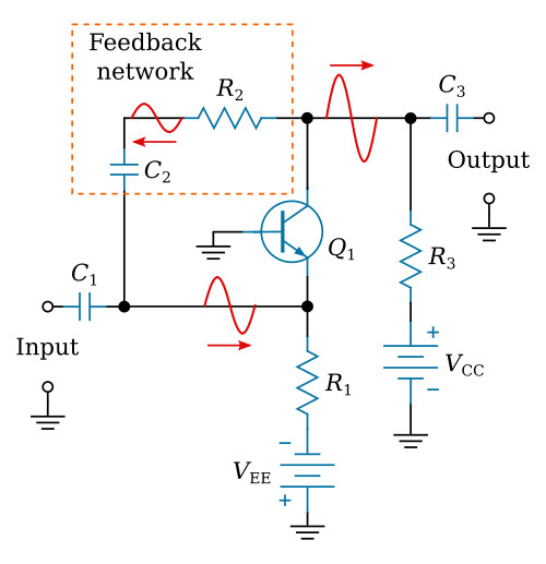
The feedback network in this amplifier is made up of R2 and C2. The value of C2 should be large so that the capacitive reactance (XC) will be low and the capacitor will couple the signal easily. (This is also the case with the input and output coupling capacitors C1 and C3.) The resistive value of R2 should be large to limit the amount of feedback signal and to ensure that the majority of the output signal goes on to the next stage through C3.
A more common configuration for transistor amplifiers is the common-emitter configuration. Positive feedback is a little more difficult with this configuration because the input and output signals are 180° out of phase. Positive feedback can be accomplished by feeding a portion of the output signal of the second stage back to the input of the first stage. This arrangement is shown in the figure below.
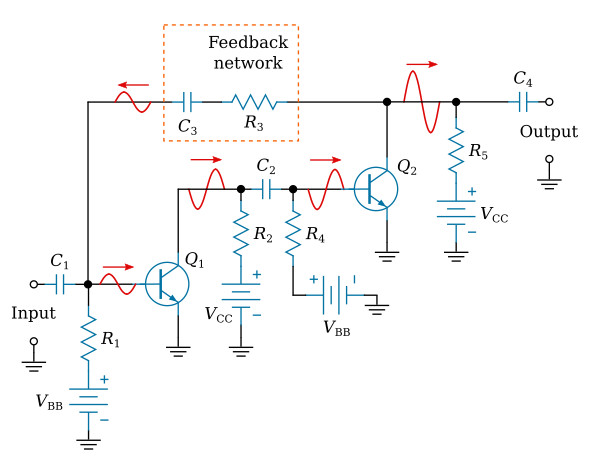
The figure shows that each stage of amplification has a 180° phase shift. This means that the output signal of Q2 will be in phase with the input signal to Q1. A portion of the output signal of Q2 is coupled back to the input of Q1 through the feedback network of C3 and R3. R3 should have a large resistance to limit the amount of signal through the feedback network. C3 should have a large capacitance so the capacitive reactance is low and the capacitor will couple the signal easily.
Sometimes positive feedback is used to eliminate the effects of negative feedback that are caused by circuit components. One way in which a circuit component can cause negative feedback is shown in the figure below.
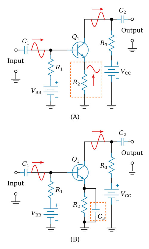
In view (A) a common-emitter transistor amplifier is shown. An emitter resistor (R2) has been placed in this circuit to provide proper biasing and temperature stability. An undesired effect of this resistor is the development of a signal at the emitter in phase with the input signal on the base. This signal is caused by the changing current through the emitter resistor (R2) as the current through the transistor changes. You might think that this signal on the emitter is a form of positive feedback since it is in phase with the input signal. But the emitter signal is really negative feedback. Current through the transistor is controlled by the base-to-emitter bias. If both the base and emitter become more positive by the same amount at the same time, current will not increase. It is the difference between the base and emitter voltages that controls the current flow through the transistor.
To eliminate this negative feedback caused by the emitter resistor, some way must be found to remove the signal from the emitter. If the signal could be coupled to ground (decoupled) the emitter of the transistor would be unaffected. That is exactly what is done. A decoupling capacitor (C3 in view B) is placed between the emitter of Q1 and ground (across the emitter resistor). This capacitor should have a high capacitance so that it will pass the signal to ground easily. The decoupling capacitor (C3) should have the same qualities as the coupling capacitors (C1 and C2) of the circuit. Decoupling capacitors are also called bypass capacitors.
Regardless of the method used to provide positive feedback in a circuit, the purpose is to increase the output signal amplitude.
Negative Feedback
Negative feedback is accomplished by adding part of the output signal out of phase with the input signal. You have seen that an emitter resistor in a common-emitter transistor amplifier will develop a negative feedback signal. Other methods of providing negative feedback are similar to those methods used to provide positive feedback. The phase relationship of the feedback signal and the input signal is the only difference.
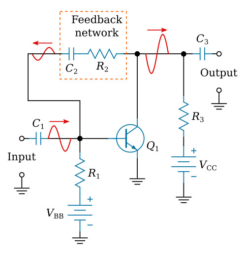
The figure below shows negative feedback in a common-emitter transistor amplifier. The feedback network of C2 and R2 couples part of the output signal of Q1 back to the input. Since the output signal is 180° out of phase with the input signal, this causes negative feedback.
Negative feedback is used to improve fidelity of an amplifier by limiting the input signal. Negative feedback can also be used to increase the frequency response of an amplifier. The gain of an amplifier decreases when the limit of its frequency response is reached. When negative feedback is used, the feedback signal decreases as the output signal decreases. At the limits of frequency response of the amplifier the smaller feedback signal means that the effective gain (gain with feedback) is increased. This will improve the frequency response of the amplifier.


