


Home > Textbooks > Basic Electronics > Amplifiers > Differential Amplifiers >
Amplifiers
Differential Amplifiers
A differential amplifier is an amplifier that can have two input signals and two output signals. This arrangement means that the differential amplifier can be used in a variety of ways. The differential amplifier can amplify the difference between two input signals. A differential amplifier will also "cancel out" common signals at the two inputs.
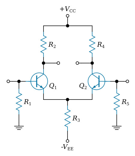
Typical differential amplifier circuit
The figure below is the schematic diagram of a typical differential amplifier. Notice that there are two inputs and two outputs. This circuit requires two bipolar transistors to provide the two inputs and two outputs. If you look at one input and the transistor with which it is associated, you will see that each transistor is a common-emitter amplifier for that input (input one and Q1; input two and Q2). R1 develops the signal at input one for Q1, and R5 develops the signal at input two for Q2. R3 is the emitter resistor for both Q1 and Q2. Notice that R3 is NOT bypassed. This means that when a signal at input one affects the current through Q1, that signal is developed by R3. (The current through Q1 must flow through R3; as this current changes, the voltage developed across R3 changes.) When a signal is developed by R3, it is applied to the emitter of Q2. In the same way, signals at input two affect the current of Q2, are developed by R3, and are felt on the emitter of Q1. R2 develops the signal for output one, and R4 develops the signal for output two.
Even though this circuit is designed to have two inputs and two outputs, it is not necessary to use both inputs and both outputs. (Remember, a differential amplifier was defined as having two possible inputs and two possible outputs.) A differential amplifier can be connected as a single-input, single-output device; a single-input, differential-output device; or a differential-input, differential-output device.
Single-input, single-output differential amplifier
The figure below shows a differential amplifier with one input (the base of Q1) and one output (the collector of Q2). The second input (the base of Q2) is grounded and the second output (the collector of Q1) is not used.
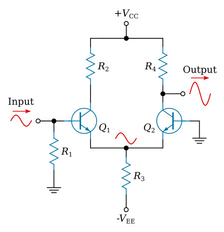
When the input signal developed by R1 goes positive, the current through Q1 increases. This increased current causes a positive-going signal at the top of R3. This signal is felt on the emitter of Q2. Since the base of Q2 is grounded, the current through Q2 decreases with a positive-going signal on the emitter. This decreased current causes less voltage drop across R4. Therefore, the voltage at the bottom of R4 increases and a positive-going signal is felt at the output.
When the input signal developed by R1 goes negative, the current through Q1 decreases. This decreased current causes a negative-going signal at the top of R3. This signal is felt on the emitter of Q2. When the emitter of Q2 goes negative, the current through Q2 increases. This increased current causes more of a voltage drop across R4. Therefore, the voltage at the bottom of R4 decreases and a negative- going signal is felt at the output.
This single-input, single-output, differential amplifier is very similar to a single-transistor amplifier as far as input and output signals are concerned. This use of a differential amplifier does provide amplification of AC or DC signals but does not take full advantage of the characteristics of a differential amplifier.
Single-input, differential-output, differential amplifier
The figure below shows a differential amplifier with one input (the base of Q1) and two outputs (the collectors of Q1 and Q2). One output is in phase with the input signal, and the other output is 180 degrees out of phase with the input signal. The outputs are differential outputs.
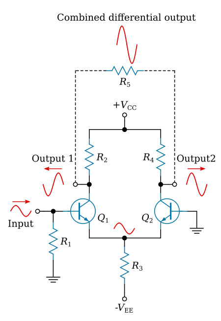
This circuit’s operation is the same as for the single-input, single-output differential amplifier just described. However, another output is obtained from the bottom of R2. As the input signal goes positive, thus causing increased current through Q1, R2 has a greater voltage drop. The output signal at the bottom of R2 therefore is negative going. A negative-going input signal will decrease current and reverse the polarities of both output signals.
Now you see how a differential amplifier can produce two amplified, differential output signals from a single-input signal. One further point of interest about this configuration is that if a combined output signal is taken between outputs number one and two, this single output will be twice the amplitude of the individual outputs. In other words, you can double the gain of the differential amplifier (single output) by taking the output signal between the two output terminals. This single-output signal will be in phase with the input signal. This is shown by the phantom signal above R5 (the phantom resistor connected between outputs number one and two would be used to develop this signal).
Differential-input, differential-output, differential amplifier
When a differential amplifier is connected with a differential input and a differential output, the full potential of the circuit is used. The figure below shows a differential amplifier with this type of configuration (differential-input, differential-output).
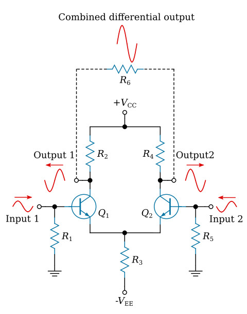
Normally, this configuration uses two input signals that are 180 degrees out of phase. This causes the difference (differential) signal to be twice as large as either input alone. (This is just like the two-input, single-output difference amplifier with input signals that are 180 degrees out of phase.)
Output number one is a signal that is in phase with input number two, and output number two is a signal that is in phase with input number one. The amplitude of each output signal is the input signal multiplied by the gain of the amplifier. With 180-degree-out-of-phase input signals, each output signal is greater in amplitude than either input signal by a factor of the gain of the amplifier.
When an output signal is taken between the two output terminals of the amplifier (as shown by the phantom connections, resistor, and signal), the combined output signal is twice as great in amplitude as either signal at output number one or output number two. (This is because output number one and output number two are 180 degrees out of phase with each other.) When the input signals are 180 degrees out of phase, the amplitude of the combined output signal is equal to the amplitude of one input signal multiplied by two times the gain of the amplifier.
The differential amplifier can have two outputs (180 degrees out of phase with each other), or the outputs can be combined as shown in the figure above.


