


Home > Textbooks > Basic Electronics > Capacitors > Capacitor Basics >
Capacitors
Capacitor Basics
In the previous section you learned that inductance is the property of a coil that causes electrical energy to be stored in a magnetic field about the coil. The energy is stored in such a way as to oppose any change in current. Capacitance is similar to inductance because it also causes a storage of energy. A capacitor is a device that stores electrical energy in an electrostatic field. The energy is stored in such a way as to oppose any change in voltage. Just how capacitance opposes a change in voltage is explained later in this section. However, it is first necessary to explain the principles of an electrostatic field as it is applied to capacitance.
The Electrostatic Field
The opposite electrical charges attract each other while like electrical charges repel each other. The reason for this is the existence of an electrostatic field. Any charged particle is surrounded by invisible lines of force, called electrostatic lines of force. These lines of force have some interesting characteristics:
- They are polarized from positive to negative.
- They radiate from a charged particle in straight lines and do not form closed loops.
- They have the ability to pass through any known material.
- They have the ability to distort the orbits of tightly bound electrons.
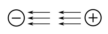
Examine the figure below. This figure represents two unlike charges surrounded by their electrostatic field. Because an electrostatic field is polarized positive to negative, arrows are shown radiating away from the positive charge and toward the negative charge. Stated another way, the field from the positive charge is pushing, while the field from the negative charge is pulling. The effect of the field is to push and pull the unlike charges together.
In the figure below, two like charges are shown with their surrounding electrostatic field. The effect of the electrostatic field is to push the charges apart.

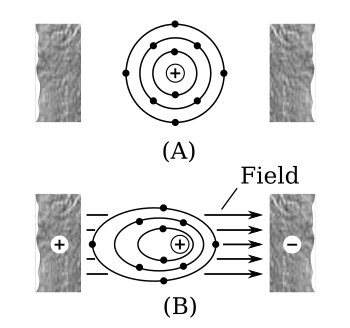
If two unlike charges are placed on opposite sides of an atom whose outermost electrons cannot escape their orbits, the orbits of the electrons are distorted as shown in the figure below. The figure below (part A) shows the normal orbit. Part (B) of the figure shows the same orbit in the presence of charged particles. Since the electron is a negative charge, the positive charge attracts the electrons, pulling the electrons closer to the positive charge. The negative charge repels the electrons, pushing them further from the negative charge. It is this ability of an electrostatic field to attract and to repel charges that allows the capacitor to store energy.
The Simple Capacitor
A simple capacitor consists of two metal plates separated by an insulating material called a dielectric, as illustrated in the figure below. Note that one plate is connected to the positive terminal of a battery; the other plate is connected through a closed switch (S1) to the negative terminal of the battery. Remember, an insulator is a material whose electrons cannot easily escape their orbits. Due to the battery voltage, plate A is charged positively and plate B is charged negatively. Thus an electrostatic field is set up between the positive and negative plates. The electrons on the negative plate (plate B) are attracted to the positive charges on the positive plate (plate A).
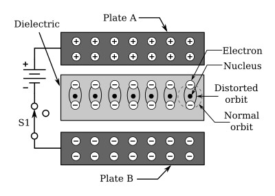
Notice that the orbits of the electrons in the dielectric material are distorted by the electrostatic field. The distortion occurs because the electrons in the dielectric are attracted to the top plate while being repelled from the bottom plate. When switch S1 is opened, the battery is removed from the circuit and the charge is retained by the capacitor. This occurs because the dielectric material is an insulator, and the electrons in the bottom plate (negative charge) have no path to reach the top plate (positive charge). The distorted orbits of the atoms of the dielectric plus the electrostatic force of attraction between the two plates hold the positive and negative charges in their original position. Thus, the energy which came from the battery is now stored in the electrostatic field of the capacitor.
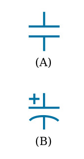
Two slightly different symbols for representing a capacitor are shown in the figure below. Notice that each symbol is composed of two plates separated by a space that represents the dielectric. The curved plate in (B) of the figure indicates the plate should be connected to a negative polarity.
The Farad
Capacitance is measured in units called farads. A one-farad capacitor stores one coulomb (a unit of charge (Q) equal to 6.24 × 10¹⁸ electrons) of charge when a voltage (V) of 1 volt is applied across the terminals of the capacitor. This can be expressed by the formula:

The farad is a very large unit of measurement of capacitance. For convenience, the microfarad (abbreviated µF) or the picofarad (abbreviated pF) is used. One microfarad is equal to 0.000001 or 1 × 10⁻⁶ farad, and one picofarad is equal to 0.000000000001 farad or 1 × 10-12 farad. Capacitance is a physical property of the capacitor and does not depend on circuit characteristics of voltage, current, and resistance. A given capacitor always has the same value of capacitance (farads) in one circuit as in any other circuit in which it is connected.
Factors Affecting the Value of Capacitance
The value of capacitance of a capacitor depends on three factors:
- The area of the plates.
- The distance between the plates.
- The relative permittivity (dielectric constant) of the material between the plates.
Plate area affects the value of capacitance in the same manner that the size of a container affects the amount of water that can be held by the container. A capacitor with the large plate area can store more charges than a capacitor with a small plate area. Simply stated, "the larger the plate area, the larger the capacitance".
The second factor affecting capacitance is the distance between the plates. Electrostatic lines of force are strongest when the charged particles that create them are close together. When the charged particles are moved further apart, the lines of force weaken, and the ability to store a charge decreases.
The third factor affecting capacitance is the relative permittivity of the insulating material between the plates of a capacitor. The various insulating materials used as the dielectric in a capacitor differ in their ability to respond to (pass) electrostatic lines of force. A dielectric material, or insulator, is rated as to its ability to respond to electrostatic lines of force in terms of a figure called the relative permittivity. Relative permittivities for some common materials are given in the following list:
| Material | Relative permittivity |
|---|---|
| Vacuum | 1.0000 |
| Air | 1.0006 |
| Paraffin paper | 3.5 |
| Glass | 5 to 10 |
| Mica | 3 to 6 |
| Rubber | 2.5 to 35 |
| Wood | 2.5 to 8 |
| Glycerine (15°C) | 56 |
| Petroleum | 2 |
| Pure water | 81 |
Notice the relative permittivity for a vacuum. Since a vacuum is the standard of reference, it is assigned a constant of one. The relative permittivities of all materials are compared to that of a vacuum. Since the relative permittivity of air has been determined to be approximately the same as that of a vacuum, the relative permittivity of air is also considered to be equal to one.
The formula used to compute the value of capacitance is:

where
C - capacitance
A - area of one plate
d - distance between the plates
εr - relative permittivity (dielectric constant) of the insulating material
ε0 - vacuum permittivity (electric constant),
ε0 ≈ 8.854 × 10⁻¹² F/m
Example:
Find the capacitance of a parallel plate capacitor with paraffin paper as the dielectric.
Given: εr = 3.5, d = 1 mm, A = 0.01 m2
Solution:

By examining the above formula you can see that capacitance varies directly as the relative permittivity and the area of the capacitor plates, and inversely as the distance between the plates.
Voltage Rating of Capacitors
In selecting or substituting a capacitor for use, consideration must be given to (1) the value of capacitance desired and (2) the amount of voltage to be applied across the capacitor. If the voltage applied across the capacitor is too great, the dielectric will break down and arcing will occur between the capacitor plates. When this happens the capacitor becomes a short-circuit and the flow of direct current through it can cause damage to other electronic parts. Each capacitor has a voltage rating (a working voltage) that should not be exceeded.
The working voltage of the capacitor is the maximum voltage that can be steadily applied without danger of breaking down the dielectric. The working voltage depends on the type of material used as the dielectric and on the thickness of the dielectric. (A high-voltage capacitor that has a thick dielectric must have a relatively large plate area in order to have the same capacitance as a similar low-voltage capacitor having a thin dielectric.) The working voltage also depends on the applied frequency because the losses, and the resultant heating effect, increase as the frequency increases.
A capacitor with a voltage rating of 500 volts DC cannot be safely subjected to an alternating voltage or a pulsating direct voltage having an effective value of 500 volts. Since an alternating voltage of 500 volts (RMS) has a peak value of 707 volts, a capacitor to which it is applied should have a working voltage of at least 750 volts. In practice, a capacitor should be selected so that its working voltage is at least 50 percent greater than the highest effective voltage to be applied to it.
Capacitor Losses
Power loss in a capacitor may be attributed to dielectric hysteresis and dielectric leakage. Dielectric hysteresis may be defined as an effect in a dielectric material similar to the hysteresis found in a magnetic material. It is the result of changes in orientation of electron orbits in the dielectric because of the rapid reversals of the polarity of the line voltage. The amount of power loss due to dielectric hysteresis depends upon the type of dielectric used. A vacuum dielectric has the smallest power loss.
Dielectric leakage occurs in a capacitor as the result of leakage current through the dielectric. Normally it is assumed that the dielectric will effectively prevent the flow of current through the capacitor. Although the resistance of the dielectric is extremely high, a minute amount of current does flow. Ordinarily this current is so small that for all practical purposes it is ignored. However, if the leakage through the dielectric is abnormally high, there will be a rapid loss of charge and an overheating of the capacitor.
The power loss of a capacitor is determined by loss in the dielectric. If the loss is negligible and the capacitor returns the total charge to the circuit, it is considered to be a perfect capacitor with a power loss of zero.


