


Home > Textbooks > Basic Electronics > Diodes > PN Junction Application >
Diodes
PN Junction Application
Until now, we have mentioned only one application for the diode - rectification, but there are many more applications that we have not yet discussed. Variations in doping agents, semiconductor materials, and manufacturing techniques have made it possible to produce diodes that can be used in many different applications. Examples of these types of diodes are signal diodes, rectifying diodes, Zener diodes (voltage protection diodes for power supplies), varactors (amplifying and switching diodes), and many more. Only applications for two of the most commonly used diodes, the signal diode and rectifier diode, will be presented in this topic.
Half-Wave Rectifier
One of the most important uses of a diode is rectification. The normal PN junction diode is well-suited for this purpose as it conducts very heavily when forward biased (low-resistance direction) and only slightly when reverse biased (high-resistance direction). If we place this diode in series with a source of AC power, then the diode will be forward and reverse biased every cycle. Since in this situation current flows more easily in one direction than the other, rectification is accomplished. The simplest rectifier circuit is a half-wave rectifier (figure below) which consists of a diode, an AC power source, and a load resistor.
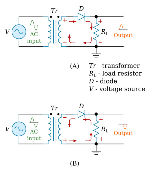
The transformer (Tr) in the figure provides the AC input to the circuit; the diode (D) provides the rectification; and the load resistor (RL) serves two purposes: it limits the amount of current flow in the circuit to a safe level, and it also develops the output signal because of the current flow through it.
Before describing how this circuit operates, the definition of the word "load" as it applies to power supplies must be understood. Load is defined as any device that draws current. A device that draws little current is considered a light load, whereas a device that draws a large amount of current is a heavy load. Remember that when we speak of "load", we are speaking about the device that draws current from the power source. This device may be a simple resistor, or one or more complicated electronic circuits.
During the positive half-cycle of the input signal (solid line) in the figure above view A, the top of the transformer is positive with respect to ground. The dots on the transformer indicate points of the same polarity. With this condition the diode is forward biased, the depletion region is narrow, the resistance of the diode is low, and current flows through the circuit in the direction of the solid lines. When this current flows through the load resistor, it develops a positive to negative voltage drop across it, which appears as a positive voltage at the output terminal.
When the AC input goes in a negative direction (figure above view B), the top of the transformer becomes negative and the diode becomes reverse biased. With reverse bias applied to the diode, the depletion region increases, the resistance of the diode is high, and minimum current flows through the diode. For all practical purposes, there is no output developed across the load resistor during the negative alternation of the input signal as indicated by the broken lines in the figure. Although only one cycle of input is shown, it should be realized that the action described above continually repeats itself, as long as there is an input. Therefore, since only the positive half-cycles appear at the output then this circuit converted the AC input into a positive pulsating DC voltage. The frequency of the output voltage is equal to the frequency of the applied AC signal since there is one pulse out for each cycle of the AC input. For example, if the input frequency is 60 hertz (60 cycles per second), the output frequency is 60 pulses per second (pps).
However, if the diode is reversed, a negative output voltage would be obtained. This is because the current would be flowing from the bottom of RL toward the top, making the output at the top of RL negative in respect to the bottom or ground. Because current flows in this circuit only during half of the input cycle, it is called a half-wave rectifier.
Diode Switch
In addition to their use as simple rectifiers, diodes are also used in circuits that mix signals together (mixers), detect the presence of a signal (detector), and act as a switch "to open or close a circuit". Diodes used in these applications are commonly referred to as "signal diodes". The simplest application of a signal diode is the basic diode switch shown in the figure below.
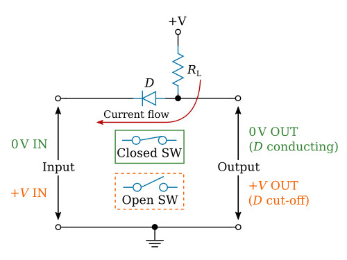
When the input to this circuit is at zero potential, the diode is forward biased because of the zero potential on the cathode and the positive voltage on the anode. In this condition, the diode conducts and acts as a straight piece of wire because of its very low forward resistance. In effect, the input is directly coupled to the output resulting in zero volts across the output terminals. Therefore, the diode acts as a closed switch when its anode is positive with respect to its cathode.
If we apply a positive input voltage (equal to or greater than the positive voltage supplied to the anode) to the diode's cathode, the diode will be reverse biased. In this situation, the diode is cut off and acts as an open switch between the input and output terminals. Consequently, with no current flow in the circuit, the positive voltage on the diode's anode will be felt at the output terminal. Therefore, the diode acts as an open switch when it is reverse biased.


