


Home > Textbooks > Basic Electronics > Inductors > Inductor Basics >
Inductors
Inductor Basics
An inductor is an electrical component the primary purpose of which is to introduce inductance into an electrical circuit or network.
Inductance
Inductance is the characteristic of an electrical circuit that opposes the starting, stopping, or a change in value of current. The above statement is of such importance to the study of inductance that it bears repeating. Inductance is the characteristic of an electrical conductor that opposes change in current. The symbol for inductance is L and the basic unit of inductance is the henry (H).
You do not have to look far to find a physical analogy of inductance. Anyone who has ever had to push a heavy load (wheelbarrow, car, etc.) is aware that it takes more work to start the load moving than it does to keep it moving. Once the load is moving, it is easier to keep the load moving than to stop it again. This is because the load possesses the property of inertia. Inertia is the characteristic of mass which opposes a change in velocity. Inductance has the same effect on current in an electrical circuit as inertia has on the movement of a mechanical object. It requires more energy to start or stop current than it does to keep it flowing.
Even a perfectly straight length of conductor has some inductance. As you may know, current in a conductor produces a magnetic field surrounding the conductor. When the current changes, the magnetic field changes. This causes relative motion between the magnetic field and the conductor, and an electromotive force (EMF) is induced in the conductor. This EMF is called a self-induced EMF because it is induced in the conductor carrying the current. The EMF produced by this moving magnetic field is also referred to as back electromotive force (BEMF). The polarity of the back electromotive force is in the opposite direction to the applied voltage of the conductor. The overall effect will be to oppose a change in current magnitude. This effect is summarized by Lenz's law which states that: The induced EMF in any circuit is always in a direction to oppose the effect that produced it.
The relationship between the induced voltage, the inductance, and the rate of change of current with respect to time is stated mathematically as:
![]()
where vL is the induced EMF in volts; L is the inductance in henrys; and Δi is the change in current in amperes occurring in Δt seconds. The symbol Δ (Greek letter delta), means "a change in ...".
Since all circuits have conductors in them, you can assume that all circuits have inductance. However, inductance has its greatest effect only when there is a change in current. Inductance does NOT oppose current, only a CHANGE in current. Where current is constantly changing as in an AC circuit, inductance has more effect.
Coil or Inductor
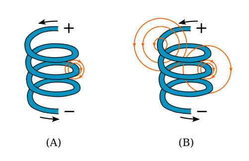
To increase the property of inductance, the conductor can be formed into a loop or coil. A coil is also called an inductor. Figure below shows a conductor formed into a coil. Current through one loop produces a magnetic field that encircles the loop in the direction as shown in view A of the figure. As current increases, the magnetic field expands and cuts all the loops as shown in view B of the figure. The current in each loop affects all other loops. The field cutting the other loop has the effect of increasing the inductance.
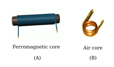
Inductors are classified according to core type. The core is the center of the inductor just as the core of an apple is the center of an apple. The inductor is made by forming a coil of wire around a core. The core material is normally one of two basic types: ferromagnetic or air. A ferromagnetic-core inductor is shown in the figure below, view A. The air-core inductor may be nothing more than a coil of wire, but it is usually a coil formed around a hollow form of some nonmagnetic material such as cardboard. This material serves no purpose other than to hold the shape of the coil. An air-core inductor is shown in the figure below, view B.
Factors Affecting Coil Inductance
There are several physical factors which affect the inductance of a coil. They include the number of turns in the coil, the diameter of the coil, the coil length, the type of material used in the core, and the number of layers of winding in the coils.
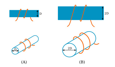
Inductance depends entirely upon the physical construction of the circuit, and can only be measured with special laboratory instruments. Of the factors mentioned, consider first how the number of turns affects the inductance of a coil. Figure below shows two coils. Coil (A) has two turns and coil (B) has four turns. In coil (A), the flux field set up by one loop cuts one other loop. In coil (B), the flux field set up by one loop cuts three other loops. Doubling the number of turns in the coil will produce a field twice as strong, if the same current is used. A field twice as strong, cutting twice the number of turns, will induce four times the voltage. Therefore, it can be said that the inductance varies as the square of the number of turns.
The second factor is the coil diameter. In the figure below you can see that the coil in view B has twice the diameter of coil view A. Physically, it requires more wire to construct a coil of large diameter than one of small diameter with an equal number of turns. Therefore, more lines of force exist to induce a back EMF in the coil with the larger diameter. Actually, the inductance of a coil increases directly as the cross- sectional area of the core increases. Recall the formula for the area of a circle: A = πr2. Doubling the radius of a coil increases the inductance by a factor of four.
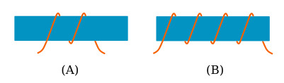
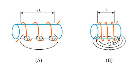
The third factor that affects the inductance of a coil is the length of the coil. Figure below shows two examples of coil spacings. Coil (A) has three turns, rather widely spaced, making a relatively long coil. A coil of this type has few flux linkages, due to the greater distance between each turn. Therefore, coil (A) has a relatively low inductance. Coil (B) has closely spaced turns, making a relatively short coil. This close spacing increases the flux linkage, increasing the inductance of the coil. Doubling the length of a coil while keeping the same number of turns halves the value of inductance.
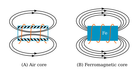
The fourth physical factor is the type of core material used with the coil. Figure below shows two coils: Coil (A) with an air core, and coil (B) with a ferromagnetic core. The magnetic core of coil (B) is a better path for magnetic lines of force than is the nonmagnetic core of coil (A). The ferromagnetic core's high permeability has less reluctance to the magnetic flux, resulting in more magnetic lines of force. This increase in the magnetic lines of force increases the number of lines of force cutting each loop of the coil, thus increasing the inductance of the coil. It should now be apparent that the inductance of a coil increases directly as the permeability of the core material increases.
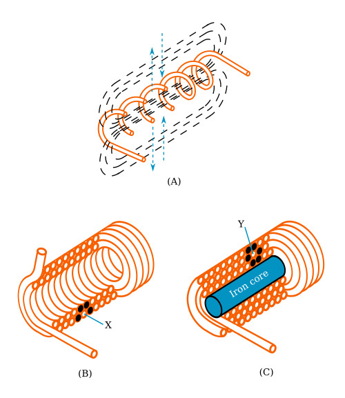
Another way of increasing the inductance is to wind the coil in layers. Figure below shows three cores with different amounts of layering. The coil in view A is a poor inductor compared to the others in the figure because its turns are widely spaced and there is no layering. The flux movement, indicated by the dashed arrows, does not link effectively because there is only one layer of turns. A more inductive coil is shown in view B. The turns are closely spaced and the wire has been wound in two layers. The two layers link each other with a greater number of flux loops during all flux movements. Note that nearly all the turns, such as X, are next to four other turns (black). This causes the flux linkage to be increased. A coil can be made still more inductive by winding it in three layers, as shown in view C. The increased number of layers (cross-sectional area) improves flux linkage even more. Note that some turns, such as Y, lie directly next to six other turns (black). In actual practice, layering can continue on through many more layers. The important fact to remember, however, is that the inductance of the coil increases with each layer added.
As you have seen, several factors can affect the inductance of a coil, and all of these factors are variable. Many differently constructed coils can have the same inductance. The important information to remember, however, is that inductance is dependent upon the degree of linkage between the wire conductor(s) and the electromagnetic field. In a straight length of conductor, there is very little flux linkage between one part of the conductor and another. Therefore, its inductance is extremely small. It was shown that conductors become much more inductive when they are wound into coils. This is true because there is maximum flux linkage between the conductor turns, which lie side by side in the coil.


